Laser engraving plays to strengths of nanosecond pulsed fiber lasers
Laser engraving is one of those applications that often gets bundled up with marking, but in reality is quite different. Engraving can best be defined as an application in which there is physical removal of material, creating a changed profile in the substrate being processed.
Applications of engraving are extremely wide-ranging and touch many aspects of everyday life, from steel to stones. The next time you are in your car and run your hands over the dashboard and interior trim, that leatherette texture that you feel has nothing to do with any animal hide. It’s created digitally and intricately engraved into the steel mold tool that is used to make these plastic components, typically using a nanosecond pulsed fiber laser. Manufacturing of coin and medal molds are also in the domain of laser engraving and in the jewelry industry, laser processing of precious metals is becoming more widely adopted. Images that people may have of craftsmen using punches and hammers to hallmark items are now becoming more of a rarity—in today’s world, it’s all being done by lasers.
Although other types of lasers such as ultrafast and even continuous-wave (CW) lasers can be used for engraving in certain applications, the vast majority of applications are served by nanosecond pulsed fiber lasers. The short duration pulses with high peak power are ideally suited to this application. In fact, master oscillator power amplifier (MOPA) designs that enable users to select pulse duration and offer up to 4 MHz repetition rates, such as SPI Lasers’ PulseTune technology offering three orders of magnitude of pulse duration control from 3 ns to 2 µs, are best suited for this use, as they give users the chance to optimize pulse characteristics for quality and/or productivity.
Achieving quality
The process is, in principle, relatively straightforward—the incident pulse of laser light melts an amount of substrate, creating a melt pool. Then, an amount of surface vaporization is achieved that creates a recoil pressure on the melt, resulting in melt ejection—the primary mechanism for material removal. At this point, it is probably worthwhile to dispel some common misconceptions that the highest pulse energies remove the most material and the highest peak powers and shortest pulses give the best quality. The process is extremely complex and there are no hard-fast rules that can be effectively applied. There is a fine balance between the pulse characteristics, the optical arrangement, and the processing/scanning parameters that need to be optimized based on end-user requirement—whether these are based on quality or removal rate, as the two are mutually exclusive.
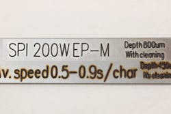
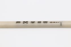
Engraving is a layer-based material removal process in which only a few tens of microns of material are removed in a single pass. The removal process is relatively slow, with removal rates being measured in cubic millimeters per minute governed by the average power that can be used. Key to achieving both high-quality surfaces and high removal rates are the machining strategies that are employed. Basic raster scanning is generally unsuitable, as it can result in the formation of furrows; unless its low depth and residual roughness can be tolerated, this process should not be used. Laser wobbling can be used if only engraved lines and simple text are required. This technique is highly applicable to applications such as vehicle identification number (VIN) marking, where significant depth is required to make the part visible after painting and also from a security perspective to make grinding off the number more difficult. In these kinds of applications, the versatility of these laser sources really comes into play. With a simple change in parameters, shortening pulse duration and increasing pulse frequency, the same laser can be used to effectively clean up the oxide and surface spatter caused by the engraving process (FIGURE 1).
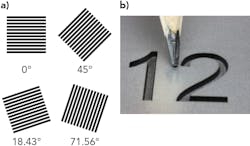
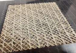
However, for larger areas and more complex geometries, a directional and layer-based strategy needs to be used to average out or randomize any directional processing effects. Some exponents just increment each successive pass by a number of degrees, and this certainly gives improved results. Using a set of fixed angles that are based on minimizing Moiré interference patterning offers the best solution; this technique has been widely used in the printing industry for many years to give even and consistent print quality, and has been shown to work exceptionally well in laser engraving (FIGURE 2).The key is in the pulse
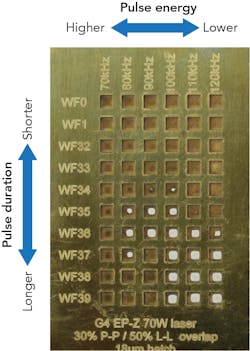
As said previously, process optimization can be a lengthy but rewarding activity that can, in some cases, double the removal rate or halve residual roughness. Not only the pulse parameters, but the geometric parameters of pulse-to-pulse (P-P) overlap and line-to-line (L-L) separation need to be considered. This optimization can to a greater extent be structured and semiautomated by the use of swatches to show the interdependencies of the selected parameters. For example, looking at brass engraving and varying the pulse duration and the pulse frequency at the same average power (while keeping P-P and L-L constant), it can be seen that the highest pulse energy, with highest peak power and shortest pulse duration, exhibits a very poor material removal rate. The swatch shows that by increasing the repetition rate to reduce both the pulse energy and the peak power, and by lengthening the pulse duration, significant improvements can be made in material removal rates—in some cases, up to 40%. What is also interesting is that if the same test is applied to different materials, then the results are different. This is perhaps not surprising, as key material properties such as conductivity, heat capacity melting point, and fluid viscosity, to name a few, are all significantly different and relevant to the process. The parameter sweet spot is therefore considerably different for aluminum and steels, so it’s a case of trial and error (FIGURE 3).Academics have proposed various models and simulations of the engraving process, but the authors have yet to see one that covers the whole range of available process parameters and range of materials—it’s truly a very complex process.
One of the big challenges is to increase removal rate while still maintaining high-quality residual surfaces. This is primarily a problem of thermal management and currently limits the amount of average power that can generally be used to between 50 and 100 W. At these power levels, heat accumulation in the part starts to give rise to a degradation in quality and consistency. There are examples where higher powers can be successfully used on larger areas where there is sufficient bulk material, such as on print rolls, but these are limited.
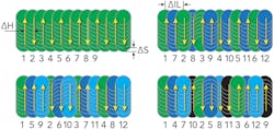
The question of thermal management can be addressed by various processing strategies to distribute the thermal load. A promising scanning-based technique is that of interlacing, where lines in a processing plane are skipped and then filled in on a subsequent pass.1 This work has shown (FIGURE 4) that when processing with 100 W laser sources, significant improvements in both material removal rates and residual surface roughness (when using interlacing compared to sequential scanning) can be achieved in aluminum and brass. However, when using this technique on stainless steel, no benefits were observed on removal rates, but surface roughness was improved. This work is now progressing to the use of 200 W with promising results.Material engraving is boundless—almost
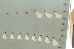
The range of materials that can be engraved are boundless, providing they exhibit a level of absorption in the infrared (IR). Engraving is not limited to metallic materials and can be used on ceramics and even carbon-reinforced plastic (CRP)-type materials. Ceramics can pose a challenge due to their brittle nature and cracking can be problematic, but some materials such as aluminum nitride (AlN) can be successfully processed with exceptional results (FIGURE 6). The laser does not see the hardness of these materials and can, for instance, process even the hardest known materials—diamonds. In the aerospace industry, the use of nanosecond pulsed lasers has been widely adopted for the selective processing of thermal barrier coating in the production of raceways into the cooling holes drilled into superalloy turbine blades (FIGURE 7).Hopefully, this article will have given a good insight into the strengths of fiber lasers and how they play a key part in modern manufacturing. That said, it is also fair to say the article has barely scratched the surface of the wide variety of benefits and advantages that engraving with fiber lasers can bring to businesses around the globe—it hasn’t even touched on the potential cost savings. For more information on fiber laser engraving, be sure to visit SPI Lasers’ dedicated engraving section at spilasers.com.
REFERENCE
1. S. Dondieu et al., “Investigation of laser beam scanning strategies for 100W pulsed fiber laser engraving of metal,” Proc. ICALEO (2019).
About the Author
Jack Gabzdyl
Industry Manager – Electronics, TRUMPF Laser UK Ltd
Dr. Jack Gabzdyl is Industry Manager – Electronics at TRUMPF Laser UK Ltd (Southampton, England) and has more than 30 years of laser materials processing experience. He obtained his PhD in laser processing from Imperial College London in 1989. He has since had a number of technical and marketing positions at BOC Gases, Advanced Laser Solutions, and TWI before joining TRUMPF (formerly SPI Lasers) in 2007.
