Understanding applications of a multifunction tool polygon scanner
Laser-based manufacturing processes are already well established in the industry. Nevertheless, these production methods need to be continuously developed to improve the quality and effectiveness of the processes. The effectiveness of a laser process depends not only on the resulting quality of the final part, but also on the time needed for the process.
Laser source developments are providing a substantial increase in the average power available for processing systems. To take advantage of these higher average optical powers, a faster beam guidance speed over the processed material is required. Commonly available laser guidance systems are based on galvanometer mirrors. These systems achieve scan speeds of around 15 m/s, limiting the potential processing rates of high-power laser processes. To scale up the scan speed, a new scan system based on polygon scanner technology was developed with scan speeds up to 1 km/s.1 Ongoing development is necessary for this system to meet the requirements of the industry.
Technological realization
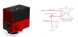
In general, the system can be separated in an optomechanical or electrical subsystem. The optical parts of the scanner are the polygon wheel, the galvanometer mirror, and the f-theta optics. In Figure 1a, a model of the complete polygon mirror scanning system is shown; a schematic illustration of the optical scheme is shown in Figure 1b.2
The resulting scan field consists of a fast axis and a slow axis. The high rounds per minute (rpm) of the polygon mirror enables an ultrafast beam deflection, called fast axis. At the intersection of the eight mirror facets the laser signal is automatically switched off by the internal electronics. While waiting for the next facet to be positioned, the galvanometer mirror jumps one-line distance further. This results in a movement called slow axis. The sum of these two motions generates a two-dimensional process area. To enhance the process quality, a special wedged double polygon mirror is used. The special characteristic of this polygon reduces the distortions caused by the f-theta optics (as explained in detail in Ref. 1).
Another helpful feature is the correction of the beam misalignment by the mirror pair of the polygon’s facets with help of the galvanometer mirror. With a unique set of compensation values for each facet, the alignment of the single lines can be optimized. The specially designed double polygon reduces the distortions generated by the f-theta optics. The heart of the electronical system is the field-programmable gate array (FPGA). With the FPGA in combination with the ultrafast electronics, the scanner reacts to external events close to real time. The configuration of the FPGA is performed via an Ethernet connection. Furthermore, an implemented general I/O interface makes the integration of the polygon scan system into a completely automatic machine possible. After the configuration of the process task, the polygon scanner can be controlled by the programmable logic controller (PLC) software via the general I/O interface. The laser is controlled by analog or digital signals via the laser I/O interface. The scanner can be synchronized with external axis systems.
During position changes of the axis systems the scanner can react in close to real time. The line scan speed v is dependent on the rotation speed of the polygon scanner motor U and the focal distance f of the used f-theta optics. The needed precision and/or scan field area for the process defines the required optic and limits the achievable in line scan speed. A bayonet optic holder makes the usage of multiple f-theta optics possible. This allows the optics to be quickly exchanged and leads to a huge flexibility of the scan system. The maximum line scan speed can reach theoretical 4.775 km/s using 2000 mm f-theta optics. In this combination, a line scan speed of up to 3 km/s was achieved. Until now, the scanner was tested using a 10 kW continuous-wave fiber laser and passed a long-term load test without any damages. Further tests of the maximum power handling ability will show the limits of the system.
Multifunction polygon scanner
The increasing average power levels of the laser systems demand faster beam guidance systems than are commonly available on the market. The polygon scanner can provide around 100X higher deflection speeds than commonly available galvanometer scanners. This reduces process times and costs in the same way. The polygon scan system can be used for numerous of different processing tasks. Drilling, structuring, engraving/2.5D machining, laser-induced forward transfer (LIFT), cutting processes, and a lot more are possible. Not only are near-infrared lasers used in combination with the polygon scanner, but also a system for ultraviolet wavelengths is available and was tested.3
For drilling processes, an exact placement of the laser pulses is needed. For this use case, the polygon scanner has a pulse-on-demand (POD) mode implemented. The polygon scanner electronics synchronized the laser I/O output signal with the position of the polygon wheel. If the exact position of the laser pulse on the surface is recognized, the I/O gives the signal to the laser pulse picker. Exactly one pulse of the pulse train is picked out and placed accurately on the workpiece. With this technique and the accuracy of the polygon scanner, it is not only possible to drill thin foils with single pulse processes, but also metal sheets where thousands of pulses are needed.
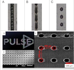
The polygon scanner was used for a high-throughput-drilling process of silicon wafers.4 If multiple pulses are necessary to penetrate the processed foil, the line of dots must be processed multiple times. At high scan speeds, the temporal uncertainty between the laser pulse picker signal and the laser pulse itself, called jitter, becomes a key factor. At static or fixed laser frequencies, the laser pulses are not synchronized with the scan system. Therefore, the pulses are applied to the material in a time span of 1/f. After several crossings, the holes are blurred out (see Fig. 2b). With a higher number of processed crossings, a linear-shaped structure is formed. To avoid this, the scan system can provide POD signals for the laser system that synchronize the polygon position with the laser system. This operation mode reduces the jitter and enables a drilling mode at high scan speeds (see Fig. 2c). In this mode, shielding effect or heating can also be minimized.Heat distribution mode
If substrates are very thin, such as metal foils, then the heat generation of the laser machining may be a problem. Due to the local heating of the thin material the foil can tear. The heat distribution mode can avoid local heating by implementing a special energy distribution in the materials. By dropping scan lines while processing the area, and later filling up these in a second over scan, the local temperatures can be lowered. Although this will increase the process time, it also opens up new process windows for high-speed processing, especially for thin-film materials. Potential application areas are the perforation or cutting of thin foils.
The polygon scanner can also be used for laser cutting applications. If the material is very thin—for example, foils—a laser cut with a common laser cutting system (melt cutting process) is not possible. An ablation cutting processes can be realized with scanner systems to increase the process speed. Furthermore, the cutting quality is excellent using ultrashort-pulsed laser systems. With the polygon scanner, the line cutting processes can be achieved faster. Foil cutting is an important application where the scanner can show its full performance.
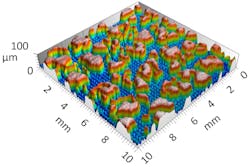
The polygon scanner is the best choice for area treatments. Hydrophobic or hydrophilic so-called functionalized surfaces are effectively generated by the polygon mirror scanner. Large areas can be modified in a short time; an area rate of 0.77 m2/min was demonstrated.5 That makes these processes highly effective. Hydrophobic surfaces are needed to reduce bacterial grow and hydrophilic surfaces for the production of slidable areas in the medical sector. As well as functional surfaces, deeper engraving processes can be realized by the polygon scanner. Using the scanner’s bitmap work mode, a 2D for area treatments or a 2.5D structuring engraving process is possible. The structure information is provided by an 8- or 16-bit bitmap.6 Each layer of the bitmap transfers information to the workpiece. In the PULSE project, a structuring process for the automotive industry has been realized with the developed scan technology. A design dataset was provided by Centro Ricerche Fiat SCPA (see Fig. 3).
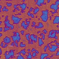
The final structure was realized layer by layer (see Fig. 4). By adapting the number of over scans per layer, the absolute depth of the final structure was successfully managed. At high laser pulse repetition rates, a low jitter appears, and sharp geometries can be structured without the need to use the POD mode.
Axis sync mode
Another novelty of the system is its integrated axes shifting registers. For each dimension, a separate encoder I/O is implemented. These are used to synchronize external axis systems with the scanner electronics. If an external axis is connected and synchronized with the scanner, the system can react on relative motions in close to real time. Therefore, it is not important if the workpiece or the scanner itself is moving. Both process situations can be programmed into the control software. The integrated shifter register can shift the scan field and/or the loaded data relative to the position. This makes large areas with highly detailed structures processable.
Bottom line
The modern polygon scan system opens a large spectrum of application areas. Benefiting from high deflection speeds, temperature-sensitive materials like foils can be drilled, perforated, or cut with high throughput. Furthermore, texturing to generate functional surfaces like hydrophobic or hydrophilic areas, engraving to generate molds for different applications, and drilling for through-contacting in the solar industry is also possible. Many processes can be performed much faster using the polygon scanner in combination with high-power lasers.
In the future, the average power levels of lasers are expected to dramatically increase. The polygon scan system provides the capabilities necessary to handle these higher powers and enables laser processing at faster speeds. The different modes of the system make it a highly attractive upgrade for state-of-the-art laser processing and fabrication facilities.
ACKNOWLEDGMENT
The PULSE project, members of which contributed to this article, is an initiative of the Photonics Public Private Partnership (www.photonics21.org). This project has received funding from the European Union’s Horizon 2020 research and innovation program under grant agreement No 824996.
REFERENCES
1. A. Streek and S. Klötzer, Sci. Rep., 4, 82–85 (2015).
2. M. Wolf, M. Müller, and A. Streek, Sci. Rep., 11, 201–204 (2019).
3. F. Rößler, M. Wolf, and A. Streek, Proc. LPM2022, 22-014, Presentation ID115 (2022) .
4. F. Rößler, M. Müller, and A. Streek, J. Laser Micro Nanoeng., 15, 3, 220–227 (2020).
5. J. Schille, L. Schneider, F. Ullmann, S. Mauersberger, and U. Loeschner, Proc. MATADOR Conf. Adv. Manuf. (2017).
6. F. Rößler, M. Müller, R. Ebert, and A. Streek, “High-power nanosecond pulsed laser engraving with an ultra-high speed polygon mirror scanner,” Hochschule Mittweida (2021).
About the Author
Marcel Wolf
Research and Development, Laser Institute of Mittweida
Marcel Wolf is in research and development at the Laser Institute of Mittweida (Mittweida, Germany).
Gianluca Deninno
Ph.D. Student, University of Turin
Gianluca Deninno is a Ph.D. student at the University of Turin (Turin, Italy).
Nello Li Pira
Global R&I Materials Manager, Centro Ricerche Fiat
Nello Li Pira is global R&I materials manager at Centro Ricerche Fiat (Orbassano, Turin, Italy).
André Streek
Professor of Laser Technology, Laser Institute of Mittweida
André Streek is professor of laser technology at the Laser Institute of Mittweida (Mittweida, Germany).


