Basics of ultrafast lasers: Part 2
In recent years, ultrafast lasers have successfully transitioned from extremely sensitive behemoths relegated to the research laboratory into compact, reliable sources suitable for integration in industrial processes. With their integration into such a wide variety of application spaces—everything from medical procedures to commercial electronics manufacturing—users from a wide variety of backgrounds now routinely operate ultrafast lasers.
Because of the unique properties of ultrafast lasers, it can be difficult for new users to know the best practices in the field. This article offers advice for using ultrafast lasers—including how to select the best optical components, an introduction to dispersion and temporal distortion, and when you should consider pulse compression.
Selecting ultrafast optical components
The technical challenges associated with ultrafast lasers can create difficulties when selecting the proper optical components for your application. The required spectral coverage, laser damage threshold (LDT), and dispersion specifications may be foreign to users accustomed to continuous-wave (CW) or longer-duration pulsed lasers.
As discussed in Part 1 of this series, generating an ultrafast laser pulse requires a broad spectral bandwidth. To illustrate this point, a Gaussian laser pulse centered at 1030 nm with 150 fs duration would require a minimum spectral bandwidth of more than 10 nm at full width at half maximum (FWHM). In contrast, the typical spectral linewidth of Nd:YAG (1064 nm) laser sources with nanosecond pulses is less than 1 nm. As a result, ultrafast laser users should ensure their optical components are sufficiently reflective or transmissive across their entire bandwidth to avoid unintended spectral (and temporal) distortion. Fortunately, most standard highly reflective or antireflective coatings are designed to operate at an appreciable bandwidth, which makes sourcing optical components for use with your ultrafast laser less frustrating (see Fig. 1).
In the most ideal case, you will be able to select an optical component with a suitable LDT rating determined under conditions as close as possible to your own operating conditions. In practice, it is likely the LDT rating for a given optic will not be determined for your exact conditions. In these situations, it is best to reach out to your optical component supplier for guidance about which optic is the best choice for your application.
Introduction to group delay dispersion (GDD)
Perhaps the most difficult challenge with using ultrafast lasers is maintaining ultrafast pulse duration. As pulse durations get shorter, the possibility of temporal distortion grows. Without diving into the mathematics that underpin this phenomenon, we can conceptualize why this is true by considering the frequency-dependence of the refractive index for a given material.
Imagine that our broadband ultrafast laser pulse is travelling through a particular medium with normal dispersion, meaning lower-frequency (longer wavelength) components travel faster than higher-frequency (shorter-wavelength) components. As our pulse travels through this material, the colors in our pulse will continue to stretch further and further apart in time.
For shorter pulse durations, and therefore broader bandwidths, this effect is further exaggerated and can lead to significant temporal distortion of our pulse. In most cases, it is convenient for us to examine this effect via the factor known as group delay dispersion (GDD), which is also known as second order dispersion. Higher-order dispersion terms may also affect the temporal profile of your ultrafast laser pulse. In practice, however, it is often sufficient to examine the impact of GDD.
The impact of GDD on your pulse duration depends on several factors, including the input pulse duration (τinput), center frequency (or wavelength), and the material through which your pulse propagates. Temporal stretching due to GDD is governed by:
From this equation, it is clear that shorter pulse durations will be more substantially broadened as compared to longer input pulses for the same amount of GDD. This explains why we never discuss GDD in the context of nanosecond or even picosecond pulses. For context, it would take 20,000 fs2 of GDD to broaden a 1 ps pulse by only 0.2%. We show in just a moment that this would be equivalent to propagating your 1030 nm pulse through more than 1 m of fused silica.
Because the refractive index of a material depends on the frequency of light, so too does the value of GDD. When selecting transmissive or refractive optics to use with your ultrafast laser pulse, it is often recommended to use fused silica, as this has one of the lowest GDD values in the visible and near-infrared (near-IR) spectral regions. For example, propagating your pulse through 1 mm of fused silica will generate ~19 fs2 of GDD at 1030 nm,1 but 1 mm of SF11 optical glass will generate more than 125 fs2 at the same wavelength.2 Refractive index databases, such as refractiveindex.info, are exceedingly helpful in determining which material is the best choice for your optical components, as well as how much GDD you are accumulating in your beam path.
Pulse (re)compression
For most ultrafast laser applications, it is rare that your pulse accumulates no GDD along your beam path. Even some reflective optics, particularly broadband dielectric mirrors, can impart some non-zero value of GDD. The question then becomes: when is it necessary to (re)compress my laser pulse? While it is impossible to provide hard and fast guidelines for every situation, an example calculation can help to demonstrate some best practices.
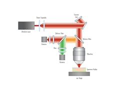
Let’s imagine we are performing a multiphoton microscopy experiment. The beam path may look similar to the one shown in Figure 3.For the purposes of calculating pulse elongation, a first order approximation may be obtained by summing the GDD contribution of all elements within the system before the laser reaches the specimen. In this schematic, let’s assume the major contributors will be the beam expander, the dichroic filter, and the objective. We will disregard the scanner mirrors, since they are typically made from low GDD metallic coatings. After identifying major contributors, we should collect the GDD contributions of all components. If our pulse is centered at 1030 nm, this system could easily contribute more than 600 fs2 of GDD.
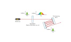
Whether or not we should recompress our pulse depends on the input pulse duration and the needs of our application. If we started with a 150 fs pulse, these optics would negligibly affect our pulse duration. If we were conducting fundamental studies and needed time resolution on the order of 10 fs, however, this amount of GDD would stretch our pulse to about 167 fs. In the latter case, we would need to recompress (see Fig. 4). Of course, these details heavily depend on your beam path and application. For assistance with choosing the best optical components for your pulse duration, contact your optical components supplier.As ultrafast lasers are integrated into a wider variety of application spaces, more users are facing the technical challenges posed by their broad spectral bandwidths, ultrahigh peak powers, and ultrashort pulse durations. No matter the application, ultrafast laser users can follow these practical guidelines to deliver their ultrafast laser pulse to the target material without decreasing their spectral coverage, distorting their temporal profile, or damaging optical components along the way.
REFERENCES
1. I. H. Malitson, J. Opt. Soc. Am., 55, 1205–1208 (1965).
2. See SCHOTT Zemax catalog 2017-01-20b (obtained from http://www.schott.com).
Olivia Wheeler
Olivia Wheeler, Ph.D., is an ultrafast laser optics engineer at Edmund Optics (Barrington, NJ).
