ANDREW KNIGHT
As semiconductor- and electronics-assembly companies push for higher levels of throughput and quality, the ability to track a printed-circuit-board (PCB) assembly throughout its manufacturing, sales, and service cycles has become very important. Many electronics vendors require that each circuit board be marked with a unique barcode identifier that can later be read by equipment that is part of an automated assembly line, warehouse shipping/receiving station, or test/rework operation. For high-volume PCB operations, laser-based marking systems incorporating automated vision systems are playing a key role in the quality and consistency of the marking process.
Barcodes have become an industry standard because of their low cost, standards and infrastructure support, high information density, and high reliability. Although barcode labels offer a cost-effective solution where small production volumes of boards are involved, higher production cycles benefit from laser scribing directly onto the base material. Laser-marked barcodes are permanent, and there is no danger of a label falling off during handling or production operations. Laser-marked codes are of superior quality. Lines are crisp and well positioned, and alignment is permanent, because there is no label to shift.
Laser-marking systems offer several advantages over ink-based approaches because the system is based only on controlling a beam of light. No tooling is involved, making software-driven laser marking systems very flexible at writing patterns. And there is nothing to wear out, so markings are consistent. Laser systems are noncontact, making marking possible in difficult-to-reach locations and making the systems friendly to delicate substrates and components. Some laser systems are ink-free, making them cleanroom compatible. All modern laser systems provide high marking speeds, low consumables costs, high process reliability, extremely low variation in character size and consistency, and high machine uptime.
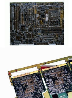
Laser marking systems are commonly used to write directly onto the surface of integrated-circuit (IC) devices. The IC packaging material on which the laser beam strikes has sufficient background contrast to make characters and logos clearly visible. Unfortunately, when writing barcodes on PCBs, this is not the case. To compensate, a light-colored ink patch is silk-screened onto the board in the area where the barcode is to be placed (see Fig. 1). Then one of two different approaches is used. A Nd:YAG laser can selectively remove ink from the circuit board to form the dark bars of the code. Alternatively, a CO2 laser can be used to change the color of special ink through a photoreactive process that produces dark bars.
Although the CO2 laser process may be less flexible than its Nd:YAG counterpart, the CO2 process does allow ink patches to be applied over copper traces on the boards without risk of damage to the circuitry. This is increasingly important as circuit and component density increases and is especially relevant to the problem of high-volume marking on high-density PC motherboards.
Machine vision and laser marking
The PCB marking process encompasses an interesting technical challenge. While the position of the etch, pads, holes, and other features of a circuit board are all tightly controlled and aligned to fiducial marks on the PCB (typically within ۪.001 in.), the position of the ink-pad labels is only loosely constrained. For motherboards and other common circuit boards, the manufacturing specification for the silk-screen target is often as much as ۪.010 or ۪.020 in., far too large to blindly write with the laser marking system. In addition, the rectangular ink pads often suffer from some undesired degree of rotation so that the barcode could actually run off the pad, leading to unreadable labels. So while the board-handling system can bring each board into position with high accuracy and high repeatability, the vision system must use some external means to locate the exact position and orientation of the ink target and feed this information to the laser marking system.
Another challenge for a marking vision system is to be able to perform quality checks and to feed good data into the existing network-based quality-management system. Such a system also needs to be user-friendly, because even in high-volume assembly operations, job changeovers are common. Programming for new assemblies or calling up existing recipes for old assemblies must be intuitive and fast.
Engineers at AB Lasers (ABL, Acton, MA) evaluated vision systems that could perform the required laser-alignment tasks and that were easily interfaced to the system`s network and control computers. One of the vision systems that met the criteria for performance, ease of use, and ease of integration was a Pentium-based Prophecy 500 industrial computer from Intelec Corp., now a division of Imaging Technology Inc. (Bedford, MA).
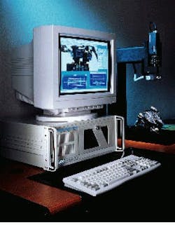
The Prophecy 500 system includes SherlockPro machine-vision software from Intelec, a peripheral-component-interconnect (PCI) bus frame grabber from Imaging Technology, and a 768 × 575 CCIR camera (see Fig. 2). During the first demonstration phase, a sales engineer trained in use of the system was able to capture an image and find the ink marks in less than 30 minutes of "programming" time, convincing our company it had an easy, yet flexible, tool to work with.
Laser marking with vision
For each type of computer motherboard, a laser setup procedure is first used to define the contents and layout of the label field itself as well as the layout of the overall board. LaserCAD, a Windows 95-based application from ABL, performs these functions. LaserCAD has a graphical user interface that allows the programming of text, complex patterns, and graphics and supports importing of drawings from many standard PC programs.
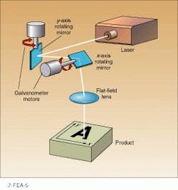
During a production run, the materials-handling system brings a new board into the laser marking machine. An image is captured by the vision system, and image-processing software determines the x, y location and theta (Q) angular orientation of all the ink targets on the board. These x, y, and Q points are then fed to the laser-beam control system. The light beam itself is aimed by computer-controlled galvanometer mirrors (see Fig. 3). The geometric equations for beam guidance are then modified in real time by software that corrects for the actual location and orientation of the target being marked. Making corrections in the beam path is simpler than trying to reposition the board.
The machine-vision system is tailored to the needs of the laser's mechanical design as well as to the requirements of PCB inspection. The laser source itself is mounted on a motorized x, y, z stage because the laser itself is capable of covering only a 4 × 4-in. area, far smaller than most circuit boards. The vision process begins when the laser moves to a location that approximates the known location of an ink target, and the image is grabbed.
Processing steps
In the first processing step, connectivity analysis is used to find all the large white objects in the field of view. Morphological operations eliminate the extraneous artwork that is often present in the field of view. An algorithm then finds the one area that is large and close to the center of the vision field of view. The connectivity analysis is run on an image that is first subject to a threshold operation using a proprietary approach that divides the field of view into grids and determines the appropriate threshold value for each grid individually. After the pad is identified, a finer analysis calculates the centroid location and draws a smooth rectangle around the pad. The edges of the rectangle are then used to calculate the angular orientation. A typical barcode ink pad might be 1.75 × 0.25 in., so a small angular variation can lead to unacceptable marks.
In the third step, the laser writes the desired barcode pattern. The last operation performs a quality check using the capabilities of PC-based machine vision. An image is grabbed after the barcode is written; this image is subtracted from the image taken just before the writing process began. Using connectivity algorithms on the barcode and character data, the vision software again determines the bounding box of the marked label and compares it to the data for the target ink pad. The system then calculates the left-right and top-bottom margins to the edges of the ink pad and compares the angular orientation of the label to the orientation of the ink target. These data are saved to a quality-control file.
Note that this vision and marking task is done individually for each mark applied to the board. The geometric relationship between the different ink pads is too loose to reference one from the other. Instead, each mark, typically two to four per motherboard, needs its own target identification and location task and quality-control check.
The vision software runs on the host's Pentium chip. No special image-processing acceleration is needed to meet the vision-processing requirements set by the machine's overall throughput rate. Images are captured by a half-size frame grabber that has been optimized for machine-vision applications. The grabber hardware uses the fast PCI bus and has a direct-memory-access-equipped interface designed for high-speed transfers to host memory. On-board image memory insures vision performance by decoupling image acquisition from other tasks the host may be performing. External triggers from the materials-handling equipment tell the vision system when to operate.
The laser marking vision system is periodically calibrated by sending a piece of anodized aluminum through the system and having the laser mark four dots in a square pattern. Connectivity algorithms define four dots, calculate their location, and then define a mathematical relationship between the pixel coordinate system of the vision system and the radian-millimeter coordinate system of the laser controller. The calibration operation also incorporates optical-distortion-correction factors to account for the fact that the vision camera operates at a 45° angle to the target, while the laser system operates at 90°. These factors are built in to the camera calibrator software.
Today's machine-vision market differs from the market of the past in that users are not interested in stand-alone inspection devices; rather, they want vision capabilities integrated into a larger manufacturing operation. The vision system must be able to send and receive parts numbers and barcode data from manufacturing data bases, communicate with other production equipment, and output quality-reporting results to statistical-control programs. Systems such as those described here are based on hardware and software standards used in the PC industry. Laser-marking-system manufacturers and other industrial users can benefit from the wide availability of low-cost hardware and software tools without worrying about being locked in to a particular vendor.


