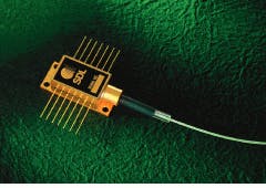
Practical applications in which the output of a diode-based laser must be coupled to an optical fiber or planar waveguide are increasing at a rapid rate. In addition to the optical-communications industry, many other laser-systems developers have found that fiberoptic beam delivery offers a number of distinct advantages over free-space propagation. In particular, fiber coupling is a convenient technique for transferring energy from high-power diode lasers for medical applications, material processing, and solid-state laser pumping.
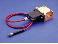
Numerous fiber-coupling techniques have been developed, but those used in commercial devices must combine high efficiency with low cost, small size, and ease of alignment. Different prioritizations of these conflicting design goals in addition to the properties of different sources and fibers have led to a number of different solutions (see photo, right). For example, techniques that are used to couple a spatially incoherent bar array to a multimode fiber for solid-state laser pumping are quite different from those used to launch the output of a distributed-feedback diode laser into a single-mode communications fiber. In both cases, however, the alignment tolerances required to accomplish the task in a small space create an optomechanical design problem that is far from trivial.
To better understand the diode-to-fiber coupling problem and some of its solutions, we will first look at the modal properties of commonly used fibers and the physics of coupling an ideal free space mode to a circular optical waveguide. In this, the simplest of cases, the astigmatism and ellipticity commonly observed in the output of diode lasers are neglected. Subsequent sections are devoted to the description of specific techniques for coupling an index-guided diode to a single-mode fiber and transferring power from high-power, spatially incoherent sources to a multimode waveguide.
Efficiencies exceed 95%
Fiberoptic waveguides that are used for communication and power-delivery applications can be classified into two broad classes depending on the number of transverse modes that can be propagated through the fiber without significant loss. On the one hand, single-mode fiber is characterized by a comparatively small core (typically less than 3 µm) in addition to a small index difference between the core and cladding layer. With such a fiber, the analysis of the coupling efficiency between an arbitrary input beam and the dominant HE11 mode has much in common with the calculation of resonator coupling coefficients for a Gaussian beam.
Multimode fibers, on other hand, have much larger cores and can transmit many low-loss modes. In contrast to single-mode fiber, which is characterized by a core diameter, index difference, and wavelength limits on the low-loss propagation of a single transverse mode, multimode fiber is generally described by core size and numerical aperture. In general, light focused into the core at an angle less than that defined by the numerical aperture will be guided, regardless of its mode structure. For this reason, multimode fiber is ideally suited for the collection and transfer of light from multistripe bar arrays and other spatially incoherent sources.
To analyze the coupling between a Gaussian free-space mode and the dominant mode of a cylindrical fiber waveguide, one first expresses the input beam in cylindrical coordinates and then evaluates two overlap integrals, the product of which is directly proportional to the coupling coefficient. Using this approach, it is possible to calculate the theoretical coupling for different fiber designs and for various misaligned configurations in which the input beam waist is translated or tilted relative to the fiber core. Assuming the reflection from the fiber endfaces is negligible, this approach gives a maximum theoretical coupling efficiency greater than 99%.1
Coupling to a multimode fiber is best described by an analogy in which the input beam is poured into a funnel defined by the core size and the numerical aperture of the fiber. More specifically, if the angular divergence of the input beam is less than the maximum angle defined by the numerical aperture of the fiber and the focused spot is less than or equal to a maximum size that is related to the core diameter, the input radiation will be coupled into the fiber.
Compact imaging schemes
In contrast to an ideal Gaussian beam propagating through free space, the output of an index-guided diode laser is both elliptical and astigmatic. For this reason, maximum coupling efficiencies are typically obtained from assemblies that incorporate at least one cylindrical focusing element. However, efficiency is not the only variable that must be considered, because overall cost and manufacturing tolerances are often more important than output power in real-world product design. Depending on the end use, coupling efficiency may be traded for cost and/or reduced alignment sensitivity.
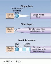
Browsing through one of the larger commercial optics catalogs—Newport Corp. (Irvine, CA) or Melles Griot (Irvine, CA), for example—will quickly convince the reader that a large number of discrete micro-optics are available for diode coupling. These include ball lenses, gradient-index (GRIN) lenses, short-focal-length aspheres, anamorphic prisms, and cylindrical lenses. In addition, there are several schemes in which the shaped end of the fiber can act as an optical element (see Fig. 1).2,3In the approach shown at the top of Fig. 1, a short-radius cylindrical lens is placed between the diode laser and fiber to reduce the divergence in the direction perpendicular to the junction. An early study by Saruwatari and Nawata theoretically and experimentally compared this simple scheme to a number of other approaches.2 Their experiments indicated that the single-cylindrical-lens approach gave the highest coupling efficiency, with measured losses of 1.8 and 1.9 dB for cylindrical lenses having radii of 12.5 and 14.6 µm, respectively.
In the approach shown in the middle of Fig. 1, the end of the fiber itself is shaped using photolithography, chemical etching, thermal melting, or mechanical polishing to produce a microlens on the fiber itself. In the best cases, coupling efficiencies comparable to those achieved with short-radius cylindrical lenses were demonstrated. In particular, a drawn taper yielded an experimental coupling loss of 1.8 dB.3
While single-element microlenses and formed fibers yield the highest coupling efficiencies, the lateral alignment tolerances for these elements are between 1 and 3 µm. Multiple-lens assemblies similar to one diagrammed at the bottom of Fig. 1 trade off coupling efficiency for alignment tolerances that are approximately an order of magnitude larger than those observed with single-lens schemes. By using a ball lens in combination with a GRIN rod lens and ‘virtual fiber’ with a GRIN lens attached to an endface, a coupling loss of -3 dB was achieved. More important, the lateral alignment tolerance of the first lens is ۯ µm in cases where the second lens and fiber/lens combination can be moved to compensate for misalignment of the first lens.4
Ultimately, the choice of a coupling scheme for a particular application is a nontrivial task. It must take into consideration the mechanical tolerances that can be held during manufacturing and the thermal and pressure effects that can lead to misalignment in the delivered product, in addition to the total amount of power that must be coupled into the fiber. In general, the added cost of supplying more front-end power to a multiple-lens assembly must be weighed against the increased fabrication costs that are associated with maintaining the tighter alignment tolerances of single-lens coupling schemes.
Microlens assemblies aid bar/array coupling
Coupling the output power of a high-power diode laser to a multimode fiber differs from the single-mode coupling task in two important respects. First, the source is highly elliptical and nondiffraction-limited in the direction perpendicular to the junction. This property precludes efficient coupling to a single-mode fiber and significantly changes the nature of the coupling problem. Second, the diameter and numerical aperture of the fiber become variables that can be optimized to achieve a desired objective.
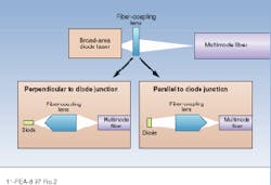
For single-emitter devices, LIMO (Lissotschenko Mikrooptik GmbH; Dortmund, Germany) manufactures a standard fiber coupler that is designed to match the output of a 100-µm-wide broad-area diode laser into a step-index fiber with a 50-µm core and a numerical aperture of 0.3. When properly aligned, this device can couple the output of a 1-W broad-area diode laser into a multimode fiber with an efficiency exceeding 90% (see Fig. 2).Multiple-element bar arrays typically consist of 10 to 20 broad-area diode lasers that are spaced equally across a 1-cm aperture. Depending on the output wavelength, the integrated CW output power from this class of device ranges from 1 W to more than 20 W, making them ideally suited for medical applications, material processing, and solid-state laser pumping. Each emitter in the bar array contributes approximately the same power to the total output and has an emitting aperture that is 100 to 200 µm wide. The output mode in the direction perpendicular to the junction (short dimension) is relatively well-behaved and diverges at an angle of approximately 30° FWHM. In the other direction it is strongly nondiffraction-limited and diverges at a FWHM angle of approximately 10°.
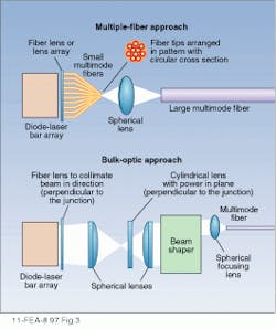
Figure 3 is a schematic representation of the two primary classes of bar-coupling schemes. In the approach shown in the top, each element of the array is coupled to an individual multimode fiber. The outputs from these fibers are then focused into a larger fiber that carries the total output power of the bar array. Typically, the diode elements are initially coupled into core diameters of approximately 50 µm, with a 400-µm multimode fiber carrying the integrated output. Coupling from the individual emitters to the smaller-core fibers is accomplished through the use of imaging optics and/or shaping the fiber itself.In the alternative coupling scheme, the output of the diode-bar array is circularized and focused into a specialized coupling optic before being imaged into multimode fiber. An example of this approach is the coupling scheme developed at the University of Southampton (England) for fiber coupling and solid-state laser pumping.6 Currently, a number of manufacturers including Blue Sky Research (San Jose, CA), LIMO, and Doric Lenses (Quebec, Canada) make the short-focal-length cylindrical lenses and lens arrays needed to realize both approaches.
Fiber-coupled emitters facilitate engineering
With both single-stripe and high-power diode lasers, a fiber-coupled package gives a clear advantage to the optical system designer. Rather than dealing directly with fiber-coupling design trade-offs that are outlined above, the optical engineer can start with the knowledge that the diode-laser input is available at the output of a standard fiber connector. In addition, redundancy can be easily built in through the use of multiple sources and a standard fiber multiplexer. Source replacement is easily accomplished without disturbing the rest of the optical system by disconnecting the fiber-coupled source and inserting a new one.At the current time, fiber-coupled sources are the standard in the telecommunications industry (see Fig. 4). They are also being used in an increasing number of power-delivery applications. Fiber-coupled arrays are commercially available from several manufacturers and are used in products such as the Spectra-Physics Millennia series of diode-pumped solid-state visible lasers. In the future, the trend toward fiber-coupled sources can be expected to continue as more manufacturers offer their laser emitters in fiber-coupled packages.
ACKNOWLEDGMENT
The author would like to thank Dr. Quan Zhang of Semiconductor Laser International Corp. (Binghamton, NY) for helpful discussions during the preparation of this article.
REFERENCES
1. D. Marcuse, Bell Systems Tech. Journal 49, 1695 (1970).
2. M. Saruwatari and K. Nawata, Appl. Opt. 18, 1847 (1979).
3. G. Wenke and Y. Zhu, Appl. Opt. 22, 3837 (1983).
4. K. Kawano, Appl. Opt. 25, 2600 (1986).
5. Microlenses, Coupling Light to Optical Fibers, H.-D. Wu and F. S. Barnes, eds., IEEE, New York, NY (1991).
6. W. A. Clarkson, A. B. Neilson, and D. C. Hanna, in OSA Technical Digest Series 8, Optical Society of America, 360 (1994).
G. J. Dixon | Contributing Editor
G. J. Dixon was a Contributing Editor for Laser Focus World.
