Stable beam delivery expands excimer laser use
An effective excimer laser beam-delivery system must satisfy precise alignment tolerances at the work surface while bringing the beam in from
a remote laser.
Todd Lizotte, Orest Ohar, Terence O`Keefe, and Chris Kelly
The market for excimer lasers continues to expand at a healthy pace, with strong growth seen in micromachining, surface treatment, microlithography, and biomedical applications. The beam-delivery systems that connect advanced excimer lasers with new applications form a critical link in the practical, commercial utilization of excimer lasers. This article discusses the special challenges of excimer laser beam delivery and presents a design approach for producing a high-performance, economical beam-delivery system.
Remote beam delivery
Many of the industrial processes that use excimer lasers must be performed in a controlled environment, such as a cleanroom. The laser used for these processes is operated in another room to avoid taking u¥expensive cleanroom space and/or to prevent compromising cleanroom integrity. Other reasons for operating the excimer laser remotely are flexibility and economy. Several workstations can time-share the output of a single laser, or, conversely, a single workstation can easily switch between excimer lasers operating at different wavelengths.
In microlithography, producing integrated circuits with feature sizes as small as 0.25 ?m requires alignment of the input beam to within 1!, with a positional tolerance of less than 150 ?m. These tolerances must be maintained with the laser located often as much as 50 to 75 ft away.
Vibrational motion causes one set of problems. Typical laboratories and cleanrooms are subject to ambient vibrations in the 10?30-H¥range; heavy equipment and machinery present in industrial environments can extend this range to as high as 250 Hz. The effects of coupling any of this vibration to a turning mirror can be severe. A mirror movement of only 20 arcsec will displace the beam by nearly 600 ?m at a distance of 10 ft.
Another problem is beam divergence. A typical excimer beam is 1 2 cm and has divergences of 5 mrad and 2 mrad. Such a beam will spread to more than 12 6 cm at 75 ft. Fiberoptic beam delivery is not possible for excimer lasers because they emit short ultraviolet (UV) radiation. The only possible approach is based on conventional optics and mechanics. The challenge is to combine these in such a way as to produce a stable, low-cost beam-delivery structure.
Minimizing vibration
One approach to overcoming vibration is to use active stabilization, in which each turning mirror is mounted on x, y galvanometers or piezoelectric actuators. These systems can be complex and expensive, and they have a tendency to oscillate because each motion of a mirror causes all the other mirrors in the system to move as they actively attempt to compensate. For these reasons, we decided to design our 3D BDS (three-dimensional beam-delivery system) with passive stabilization.
Most mirror-based delivery systems use a tubular design; the tube that protects and purges the beam path is also used to connect the various mirror mounts. But tubular structures tend to resonate, that is, they pick u¥and amplify ambient vibrations. So, while this approach is acceptable for lower-precision cutting using carbon dioxide (CO2) lasers over short optical paths, it cannot deliver the performance required for excimer laser applications.
Our solution has been to use a superstructure to stabilize the beam-delivery system. Extruded aluminum struts are connected to form a rigid, continuous frame (see photo on p. 163). For lower-precision applications, we use 1 1-in. extrusions to create a superstructure with an 8 8-in. cross section. For the most demanding applications, a
12 12-in. superstructure is created from 2 2-in. extrusions. The superstructure is extended to form vertical support pedestals at various points. These terminate in 1.5-in.-thick solid aluminum footpads that sit directly on the floor.
In both formats, all mirrors and lenses are mounted on custom-made heavy optical blocks. These are large, adjustable solid-aluminum optical mounts. Commercial off-the-shelf mounts proved to be too susceptible to thermal drift and vibrational instability or were simply too expensive for this application. These optical blocks and the purge tube are then mounted inside the open superstructure.
Such a relatively massive design is in itself fairly resistant to ambient vibrations. However, any structure will amplify vibrations if stimulated at its resonant frequency. The answer is to design a system with few resonant modes at ambient frequencies and to ensure that the optics are mounted at the nodes of these modes. These resonances are easily manipulated by adjusting the length and angle of the various cross braces. This is carried out by analyzing the shape, phase, amplitude, and frequency of the vibrations in various test structures using finite element analysis?the same methodology originally developed to analyze airplane wing flexing and used for many years to design vibration-isolation tables.
The beam path of the 3D BDS itself is enclosed in thin-walled, 2.5-in.-diameter aluminum tubing, which protects the optics from dust and permits purging of the beam path with nitrogen. To prevent these tubes from transmitting vibrations, they are connected to each optical mount by a flexible bellows instead of a rigid seal.
Reducing divergence
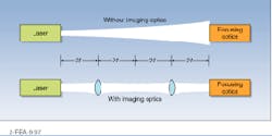
In order to minimize beam divergence, several 1:1 imaging optics are used (see Fig. 1). A lens of focal length f is placed a distance 2f from the output of the laser. This lens reimages the output of the laser at a distance 4f with unit magnification, thus negating any beam divergence over that distance. A second lens, again placed at a distance 2f from the internal focus, reimages the output of the laser at the input to the laser workstation. For our longest systems, we simply use a repeat arrangement with four lenses.
Because the laser is not being focused to a small spot, air breakdown is generally not a problem; additionally, the beam path is usually purged with nitrogen. To avoid damage to optics, mirrors are not placed at this internal focus.
Using antireflection coatings on the lenses and high-efficiency, all-dielectric reflective coatings on the mirrors maintans an overall transmission of approximately 80%, depending upon system complexity. In the simplest systems, the coatings are just optimized for a single excimer wavelength (for example, 193 nm) and an alignment laser wavelength (for example, 670 nm). In branched systems using multiple lasers, polarizing or dichroic beamsplitters are used to combine these beams. The coatings on subsequent optics must then be optimized for three, or even four, wavelengths.
Diamond-coating metals
A novel application for this beam-delivery system was recently developed by QQC Inc. (Dearborn, MI). QQC has developed and patented a method of generating a diamond coating on both ferrous and nonferrous metals. This technology can have a potentially large economic impact on the machine-tool and automotive industries, among others. Interest in the technology has been so strong that this company has already placed an order for $1 million dollars worth of excimer lasers.
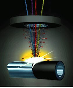
In the QQC method, the light from several lasers is simultaneously focused on the surface to be coated. In high-carbon steels, this causes carbon to migrate to the surface, where it forms a diamond layer (see Fig. 2). With low-carbon metals, CO2 gas is directed onto the surface from a nozzle in order to form the film.
QQC diamond films can be u¥to
500 ?m thick and are characterized by two important properties?high purity and exceptional adhesion. Given the difference in mechanical properties between diamond and graphite, high purity is important for mechanical durability. QQC films typically have a diamond content exceeding 99.5%. Also, the process produces a true metallurgical bond between the diamond and metal; the naturally graded interface circumvents the normal adhesion problems due to lattice mismatch.
The most significant aspect of the QQC process is that it does not require a vacuum chamber?it is carried out in the open air. This makes the technique faster, more economical, and easier to implement than methods that do require vacuum, such as plasma deposition. For example, a 2 2-cm cutting tool insert can be coated with a 45-?m-thick diamond film in 45 s. As QQC?s system can process several parts simultaneously, high throughput production is possible.
Manuel Turchan, CEO of QQC, says, ORuggedness, flexibility and tight process control were the reasons we chose the 3D BDS beam-delivery system. While we are not dealing with the micron-level precision of the semiconductor industry, with parts as small as
2 2 mm, we do need to eliminate gross jitter in order to produce consistent, uniform coatings.O Turchan adds that, because the QQC process uses several laser beams, including excimer, at multiple wavelengths, OWe needed a modular approach that would allow us to redirect multiple laser beams to different cells as needed.O
Excimer lasers promise to be useful for an expanding range of industrial processing and biomedical tasks. However, the practical employment of excimer lasers is complicated by their combination of high power, large beam divergence, and UV wavelength. The design and construction of systems that can reliably deliver this light represent one of the less-glamorous, but nonetheless important, tasks necessary to fulfill the potential of excimer laser technology. o
A rigid superstructure is the key to ultrastable excimer laser beam delivery.
FIGURE 1. The 3D BDS excimer laser beam-delivery system uses a series of 1:1 imaging optics to minimize beam divergence.
FIGURE 2. In an application developed by QQC (Dearborn MI), multiplexed laser beams focused through the 3D BDS beam-delivery system (top) into a vortex of gaseous reactants (middle) trigger a metallurgical process that produces a highly adherent diamond coating on a rotating high-carbon steel workpiece (bottom).


