Bent waveguides improve DFB laser performance
Bent waveguides improve DFB laser performance
When properly designed, lasers including bent
waveguides reach higher output powers and lower linewidths than conventional distributed-feedback diode lasers, offering an alternative for
telecommunication sources.
Hartmut H. Hillmer
Diode lasers are important components of fiberoptic communication systems. Some communications applications require special lasers with properties tailored to specific purposes. A new design tool developed at Deutsche Telekom (Darmstadt, Germany) provides additional degrees of freedom to tailor distributed-feedback (DFB) laser properties by individual axial pitch variations, creating chirped DFB gratings by using specific bent waveguides. Our low-cost method can be generally applied and generates continuously and arbitrarily chirped DFB gratings of ultrahigh spatial precision.
Compared to conventional straight-waveguide DFB lasers, the bent-waveguide principle is suitable for applications such as lasers based on a new wavelength-tuning concept with enhanced tuning and lasers with axially distributed phase shifts showing higher output powers, smaller linewidths, improved single-frequency stability at higher bias, and enhanced yield.
In recent years, semiconductor lasers based on DFB gratings have attracted considerable attention and have advanced to become key components in modern telecommunication systems. In contrast to conventional Fabry-Perot lasers, which provide the feedback by facet reflections, in DFB lasers the feedback is distributed throughout the cavity by the use of a grating; their microstructure is such that the real or imaginary part of the refractive index (or both) varies periodically in the direction of the propagating light (in the axial direction).
By the interaction of the counterpropagating waves a mode is selected, determined by the predefined pitch length of the DFB grating. Single-frequency oscillation can be easily obtained by embedding one or several additional phase shifts into the grating. This performance is important in, for example, fiberoptic transmission systems at 1.55 µm. Thus, the DFB grating acts as a filter with a specific spectral filter function.
Almost all lasers used in modern telecommunication systems include gratings with axially constant pitch length. DFB gratings with axially varying grating pitches (chirped gratings) have been studied and applied rather infrequently because a general and practical implementation method was not available.1-3 Chirped DFB gratings, however, are attractive for telecommunication systems because they open up various additional degrees of freedom in device design and performance. Using chirped DFB gratings, many device properties can be improved and specially tailored by choosing individual chirping functions [axial pitch length variation L(z)].
Recently, we proposed a simple and practical method to generate arbitrarily and continuously chirped DFB gratings with ultrahigh spatial precision.4-6 This method is described below for two different types of lasers: DFB lasers with axially continuously distributed phase shifts and multiple-section DFB lasers with enlarged electronic wavelength tuning ranges.
Principles of the bent-waveguide method
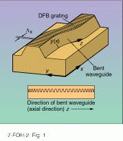
The bent-waveguide method uses bent waveguides on homogeneous DFB grating fields. First, a standard DFB grating with constant pitch length Lx in the x direction is defined by, for example, holographic techniques. Next, the optical waveguides of the laser devices are defined photolithographically by a set of masks including specifically bent stripes and subsequent etching processes (see Fig. 1).
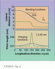
The main difference from conventional DFB lasers having straight waveguides is the use of waveguides that are bent along the curved axial coordinate z according to specific bending functions y(x). Depending on the local tilt angle q between the waveguide and the grating lines, the effective pitch length L[q(x)] = Lx /cos[q(x)] varies locally (see Fig. 2). Close to the cavity center, the angle q shows the largest values (see Figs. 1 and 2, top) leading to the maximum values of the effective pitch length in the center (see Figs. 1 and 2, bottom).
By choosing different bending functions y(x), various chirping functions L(x) can be generated with ultrahigh spatial precision. This method enables differences (Lmax - Lx) between the longest and shortest pitch in a laser cavity as small as 0.001 nm. The largest differences (~5 nm) are limited by optical bending losses. Hence, this method covers a wide chirping range (Lmax - Lx ) between 0.001 and 5 nm.
Because many applications require chirped DFB gratings with a chirping range between 0.2 and 2 nm, the bent-waveguide method can fulfill these requirements.This method enables the implementation of arbitrary chirping functions, is much easier and less expensive than electron-beam lithography, is not limited to a particular design or geometry of the DFB-based laser devices, and is thus attractive for device production.
In the production process it is only necessary to replace the set of masks used for the lithographical definition of the waveguide; instead of masks with straight stripes (for straight waveguides in conventional lasers), masks including bent stripes have to be used (for bent waveguides embedded in the novel laser type). Therefore, no additional production costs are involved for the bent-waveguide laser.
Lasers with axially distributed phase shifts
Figure 2 shows two examples of
S-shaped waveguides, illustrating the generation of axially distributed phase shifts. Note that the vertical and horizontal scales in the figure are different. The maximum bending angles for the two examples are 2.6° and 6.4°. The total phase shift included in the grating is given by the summation of p(Li / Lx - 1) over all i, numbering all the pitches inside the laser cavity. In Figure 2, both examples generate a quarter-wave phase shift that is distributed over the entire cavity length (blue) and over 1/6 of the cavity (green). The amount of phase-shift distribution markedly influences the axial profiles of the carrier- and photon-density distributions that determine the device properties and performances.
Applying moderate bending radii greater than roughly 200 µm and small maximum tilt angles less than about 10°, the bent-waveguide DFB lasers show nearly the same threshold currents as straight-waveguide lasers of identical length.5 This indicates that bending losses are negligible and thus emphasizes the effectiveness of the method.
Bent-waveguide DFB lasers have some advantages over conventional straight waveguide lasers. The carrier-density distributions are better homogenized leading to an efficient reduction of spatial hole burning at higher injection current. Therefore, bent-waveguide DFB lasers show a reduced probability of suffering from mode jumps at higher bias and reveal a considerably improved single-frequency stability. This is an important laser property because it causes a higher yield and enables the production costs to be reduced.
Because spatial hole burning can be efficiently reduced in bent-waveguide DFB lasers, they are able, if properly designed, to reach higher output powers and, therefore, lower optical linewidths than conventional lasers. In addition, the bent-waveguide laser properties do not degrade seriously if the total amount of phase shift is changed by 䕖%. Furthermore, technological uncertainties during the production process may also be well tolerated. Thus, the laser is robust against moderate geometrical or compositional changes. Another important property found in bent-waveguide DFB lasers is that a continuously distributed quarter-wave phase shift is no longer a value of outstanding significance. On the contrary, values apart from a quarter-wave phase shift can be much better choices. So, the shape of the bending function, the total amount of phase shift, and the degree of phase-shift distribution can be used to tailor individual laser properties.
Tunable DFB lasers
In recent years, a large number of different tunable lasers have been reported with, in part, very large wavelength tuning ranges, but very complicated structures. Compared to these lasers, multiple-section DFB lasers with straight waveguides have a relatively small tuning range (typically 1-2 nm). However, DFB lasers have high output powers, low linewidths, relatively simple control of the wavelength tuning, less complicated technological processing, and considerably lower production costs compared to the above-mentioned tunable laser structures. Hence, apart from the weak tunability, DFB lasers have attractive device properties.
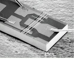
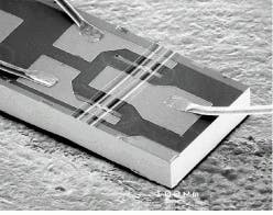
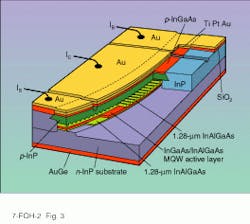
Without an increase in production cost, the Deutsche Telekom Research Center has increased the wavelength tunability considerably to 5.5 nm with the bent-waveguide structure (see Fig. 3).6 In this case, the waveguide bending was optimized to enhance the wavelength tunability. The concept of these tunable DFB lasers is based on two mechanisms: the DFB chirping function is optimized to level and homogenize the threshold gain of several spectrally neighboring modes. A single mode is selected and tuned by multiple-electrode biasing. The laser structure is fabricated in the InGaAs/ InAlGaAs material system on n-InP substrates and contains nine quantum-well films. According to Fig. 3, the sections have individual contact pads and are driven by the currents IS, IC, and IB .
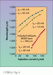
Figure 4 shows the experimental wavelength tunability of a three-section bent-waveguide DFB laser. Each of the three branches identified by a particular color corresponds to a different mode. A conventional straight-waveguide DFB laser would show a wavelength tunability that resembles that of one of these branches. That is, the tunable bent-waveguide DFB laser shown in Fig. 4 combines the tuning range of three individual conventional multiple-section DFB lasers (see photo on p. 117). A total wavelength tuning range of 5.5 nm without any wavelength gaps is shown requiring only three different modes. The side-mode suppression ratio is always between 30 and 43 dB.
Compare these results with those obtained from other bent-waveguide lasers: a tuning range of 4.3 nm with a two-electrode laser without gaps in wavelength addressing four different modes, a tuning range of 11 nm with gaps in the wavelength range, a tuning range of 2 nm using a single tuning current, and a side-mode suppression between 43 and 48.4 dB. Note that a sufficiently high side-mode suppression is obtained that guarantees a proper single-mode operation using multiple-electrode biasing. This laser can be produced at the same cost as a conventional straight-waveguide DFB laser; however, it combines the tunability of three conventional DFB lasers. n
REFERENCES
1. A. C. Livanos, A. Katzir, and A. Yariv, Optics Commun. 20, 179 (1977).
2. P. Zhou and G. S. Lee, Electron. Lett. 26, 1660 (1990).
3. A. Suzuki and K. Tada, Thin Solid Films 72, 419 (1980).
4. H. Hillmer, K. Magari, and Y. Suzuki, Photonic Technol. Lett., 5, 10 (1993).
5. H. Hillmer, A. Grabmaier, S. Hansmann, and H. Burkhard, Electron. Lett., 1483 (1994).
6. H. Hillmer et al., Appl. Phys. Lett. 65, 2130 (1994)
Scanning electron micrograph shows a bent-waveguide tunable DFB laser.
FIGURE 1. Arbitrarily chirped DFB gratings can be implemented by bent waveguides (top). The corresponding axial pitch variation can be seen looking at the cross section along the curved coordinate z (bottom).
FIGURE 2. Two bending functions y(x) [different scaling in x- and y-direction] are depicted here. The stripes schematically show the magnified homogeneous grating field. The corresponding axial pitch-length variations are displayed at the bottom.
FIGURE 3. Three-section DFB laser includes a bent waveguide to generate a specially chirped DFB grating, enhancing the electronic wavelength tunability.
FIGURE 4. Experimental wavelength tuning is shown as a function of the injection current in the center section of a distributed-feedback laser.
HARTMUT H. HILLMER is deputy of the optoelectronic device grou¥and scientific leader of the molecular beam epitaxy facility, Deutsche Telekom, Forschungszentrum, POB 100003, 64276 Darmstadt, Germany.
