Reflective optical sensors are used to sense the presence or absence of a distant object and generally consist of four elements: drive and control electronics, an optical source, an optical detector, and an optical lensing system (see Fig.1). Examples of reflective sensors used in a variety of industrial and consumer products include barcode scanners and proximity sensors.
More recently, designers have become interested in making an optical encoder component to replace the electromechanical encoders used as input devices in a number of portable electronic applications, including cell phones, laptop computers, and PDAs. Sensors for these applications represent a new subclass of reflective optical sensors and are based on laser speckle, interferometric methods, and, more recently, using self-mixing and the Doppler effect.1, 2, 3, 4 We will focus first on the packaging and optical-source choices for reflective sensors in general, and then describe one of the new sensors based on a vertical-cavity surface-emitting laser (VCSEL) and phototransistor in a single TO-style package.
Sensor design
The packaging of optical reflective sensors can be quite compact, and in the case of some LED sources, can even be packaged in a single TO can. However, a significant disadvantage to these devices is the quantity of optical crosstalk that may degrade the signal-to-noise ratio (S/N) in the detector.
Crosstalk results from the fact that LEDs emit from all surfaces and the emission subtends nearly 90°. Suppliers go to great lengths to isolate the LED and the detector by using a mechanical structure to separate the optoelectronic components. In addition, the LED optical output is not easily collimated or focused to a spot to increase the amount of reflected light from a distant object.
When more-sensitive measurements are needed, the designer often must come up with a system in which the optical source and receiver are not packaged together. This configuration reduces the quantity of optical crosstalk in the system, and may allow the designer to use laser sources. The laser source typically used is the so-called CD laser or edge-emitting laser that is used in high volume in optical data-storage applications. These lasers have several disadvantages, including a rather divergent, elliptically shaped beam that can require complex lensing to focus or collimate, and difficulty of incorporating it into a single package with the photo receiver.
Available since 1996, VCSELs eliminate the problems associated with edge-emitting lasers. Because of their high modulation speeds and high reliability, VCSELS have become the laser source of choice for multimode fiberoptic data-communications networks.5
VCSEL-based reflective sensors
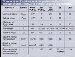
There are two types of VCSEL—single-mode (SM) and multimode (MM). The modal nature here refers to the transverse-mode structure of the laser, which is controlled by the size of the VCSEL active area. The single-mode VCSEL offers the advantages of being the most efficient and coherent device with the narrowest divergence, but it suffers from emitting the lowest total power of the three laser sources (see table).
By using the technical features of the VCSEL, integrating a phototransistor in the package, and designing the optical element into the TO can lid, an effective reflective sensor can be developed. The advantages of the sensor include the ability to package the entire assembly in a single compact TO can, along with the focusing optics and a phototransistor (see Fig. 2). Depending on the application, a single-mode or multimode VCSEL can be used. In some cases, when coherence of the optical beam is desired, the single-mode VCSEL might be the best choice, but in other cases when total output power is more important, a multimode VCSEL might be more beneficial.
For example, a multimode VCSEL can be mounted on the centerline of the lens and package, and the phototransistor mounted to the side of the VCSEL. In this configuration, the optimal signal is obtained by tilting the package with respect to the centerline of the TO. The optical system is made by including a melt-formed glass lens in the TO lid. The lid can be designed to accept other lenses, and the height can be varied, which allows for the design of a wide variety of optical sensors.
In this example, we have implemented a focusing system that creates a focal spot about 15 mm from the lens surface. The VCSEL is driven with a simple constant current source to deliver approximately 1-mW total optical power. The phototransistor is biased with 5 V on the collector, and the emitter is grounded. The current into the collector is the measured sensor response. Alternatively, the emitter can be connected to a resistance to ground, and the voltage across the resistor can be monitored.
Typical S/N values obtained with the sensor are more than 20 dB, which is very difficult to achieve in reflective sensors. The S/N could be increased even more with the use of antireflection coated optics if desired. The high S/N and the compact focal spot make this optical sensor appropriate for difficult sensing environments, or when the object to be sensed does not provide a strong reflection. This sensor is particularly well suited for the detection of round objects, dirty objects, and other low-specular-reflection objects for which traditional LED sensors are limited.
Performance characteristics
To characterize the performance of the sensor, we measure the S/N as a function of four alignment variables ρ, θ, φ, and z (see Fig. 3). Mathematically, the response of the reflective sensor can be expressed as,
where N is the background noise level in the phototransistor, A0 is the efficiency factor, z0 is the focal length of the lens, ρ0(z), θ0(z), φ0(z) are the positions of the angular reflectance maxima at the various distances, and sx represents the tolerance for each degree of freedom. The values for A and s depend on the properties of the reflector, and z0 and ρ0(z), θ0(z), φ0(z) depend on the optical design and the placement of the optoelectronic chips in the header.
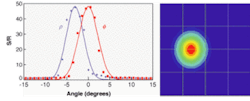
In this design example, the tolerance on both q and z are quite large (about 30° and 10 mm, respectively) because of the large phototransistor used. It is conceivable that an even larger phototransistor could eliminate the variance caused by these two degrees of alignment freedom. For the complete response, the response of the two angular displacements must be multiplied together (see Fig. 4).
For example, we sensed a 1-mm diameter pin using a traditional "arrowhead" LED and detector-pair sensor and then with the VCSEL sensor. Primarily because of the smaller spot (0.5 mm for the VCSEL, 7 mm for the LED), we achieved a 13-dB increase in the S/N, as well as improved position resolution.
In addition to the reduced power consumption and single-package interface, the recurring theme in the application is the ability of the VCSEL sensor to provide higher S/N in environments where the LED sensor is not able to adequately perform. Other application areas include the sensing of diffuse reflective surfaces such as paper in a printing system, or low-reflectivity surfaces such as glasses or plastics. The small focal spot also has significant advantages in optical encoding applications such as barcode reading or positioning equipment.
REFERENCES
- S. G. Hanson, et al, Proc. SPIE 3824, 115 (1999).
- B. Horowitz, Laser Focus World (October 1996).
- O. Kinrot et al, Laser Focus World (March 2000).
- R. Duijve et al, SID Digest, P-50.5L (2000).
- J. A. Tatum, et al, Proc. SPIE 3946, 2, SPIE, Bellingham, WA, 2000
JIM TATUM is lead engineer and strategic marketing manager and RON CHANDLER and BRENT STAPLETON are senior engineers at Honeywell VCSEL Optical Products, 830 E. Arapaho Rd., Richardson, TX 75081; e-mail: [email protected].


