A guide to group delay dispersion for ultrafast lasers
Ultrafast lasers are characterized by pulse durations ranging from picoseconds (ps) to femtoseconds (fs), and these ultrashort pulses are possible due to the laser’s broad spectral bandwidth. A minimum spectral bandwidth is required for a laser pulse to achieve a certain ultrafast duration, governed by the time-bandwidth product.
This relationship, discussed in the Basics of Ultrafast Lasers series (Part 1),1 means that maintaining an ultrafast pulse duration necessitates preserving the laser’s broad spectral bandwidth.
Related Article
Origins of (group delay) dispersion
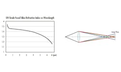
If you are familiar with the rock band Pink Floyd, you are no stranger to dispersion. The same effect that causes white light to split into a rainbow through a prism also complicates focusing that light through a single lens. Because refractive index varies with wavelength, different wavelengths of light focus at different physical locations when passing through an optical medium. For example, the refractive index of ultraviolet (UV) fused silica as a function of wavelength is shown in Figure 1a. The effect of passing different wavelengths of light through a single material lens is shown in Figure 1b.
For ultrafast lasers, we approach this from a temporal perspective. Imagine a pulse with multiple wavelength components traveling through a medium. Within this context, the medium applies different phase shifts to different wavelengths, a phenomenon known as group delay dispersion (GDD).
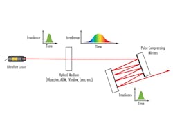
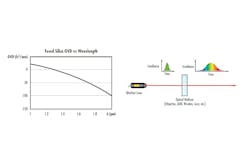
The group velocity dispersion (GVD)—or GDD per unit thickness—for fused silica is shown in Figure 2a. Just as chromatic dispersion affects where a lens focuses each color, GDD affects when the pulse’s wavelength components emerge from the optical medium. This effect is illustrated in Figure 2b, where an ultrafast laser pulse exits a medium with red portions emerging before blue ones due to positive GDD. In other words: GDD provides a quantitative measure of how different wavelength components are delayed passing through an optical medium of a given thickness.
The impact of GDD on a pulse depends on the input pulse duration: the shorter the input pulse, the more it stretches for a given GDD. Equation 1 expresses this relationship:
Greater GDD also causes more significant stretching of the input pulse.
How much GDD is in my system?
Assuming you start with a compressed pulse from your ultrafast laser system, the major sources of GDD within your optical path will be your optical components A good first estimate of the GDD in a particular system involves measuring the GDD contribution of each transmissive component.
You can do this by measuring each component with a white light interferometer for GDD characterization2 or by estimating based on substrates and thicknesses. For instance, if you have a 3-mm antireflective-coated fused silica window in your path, estimate its GDD by looking up the GVD of fused silica at the center wavelength of your pulse. Refractive index databases, such as refractiveindex.info, provide such information.
Multiply the GVD by the medium’s thickness—3 mm in this example—to estimate the GDD for your window. To closely approximate how much your input pulse may be stretched, repeat this procedure for all transmissive elements within your system, sum all the individual GDD contributions, and evaluate Equation 1 with this value.
When using very short pulses (around 50 fs or shorter), this approximation may begin to break down. At these durations, contributions from reflective components like mirrors that are not optimized for ultrafast applications or additional dispersion effects may significantly impact pulse duration.
How can I avoid GDD in my system?
Transmissive components within an optical path are major contributors to GDD. Where possible, it is best to avoid transmissive components and instead opt for reflective elements.
Many applications, however, require transmissive components. In these cases, minimize GDD by selecting thin elements made from optimal materials like fused silica for pulses in the visible and near-infrared (NIR). For example, a thinner fused silica lens is preferable to a thicker BK7 lens because it contributes less GDD. If optical performance constraints prevent using thinner elements, you can compensate for GDD by using components that apply GDD with equal magnitude but opposite sign.
For very short pulses, even reflective components with non-ultrafast coatings may impart unwanted GDD and cause significant temporal distortion. In these cases, opt for mirrors optimized to apply minimal GDD to the incident pulse (see Fig. 3).
How can I compensate for GDD?
Despite efforts to minimize transmissive components and choose low-GDD coatings, residual GDD often remains. If your stretched pulse duration is too long for your application, you will need to recompress the pulse by compensating for some or all of the GDD of your optical components.
Various approaches to pulse recompression include highly dispersive mirrors, chirped mirror pairs, gratings (transmissive and reflective), and prisms. For more information on how each of these optics can recompress an ultrafast laser pulse, please see the Basics of Ultrafast Lasers series, part 3.3
Related Article
The best strategy to compensate for applied GDD depends strongly on the application. The following section presents three hypothetical (but very realistic!) scenarios to illustrate factors to consider when implementing a particular pulse recompression strategy:
Fixed optical path with known GDD contributions. In this scenario, the elements of the optical path are fixed, and their GDD contributions are well known. A situation like this may arise for an OEM laser integrator designing equipment for ultrafast laser micromachining.
The integrator knows the customer needs a pulse duration of 100 fs at 515 nm to effectively ablate their target material, but the beam expander, scanning lens, and various filters in the optical path have stretched the original pulse to around 250 fs.
To return to the target pulse duration, the integrator must compensate for the ~8300 fs2 of GDD applied by these optical components. Because the specifications of this system are fixed, using some highly dispersive mirrors in this optical path would be a good option to recompress this pulse.
Bouncing the stretched pulse 8 times on a highly dispersive mirror that applies -1000 fs2 of GDD per bounce would compensate for most of the applied GDD in this system. While this approach leaves 300 fs2 of residual GDD, the 100-fs pulse duration is negligibly affected by this amount of dispersion.
Broad spectrum and rough estimates of GDD. Consider a situation where the laser pulse spectrum is exceptionally broad, and the duration is exceptionally short. Reflective components with low GDD have been used throughout the entire optical path, but a focusing objective is critical to achieve a very high photon flux at the sample plane.
This situation is not uncommon for the multiphoton microscopist, who takes advantage of the exceptionally high peak powers of ultrafast lasers to generate detailed images of biological samples.
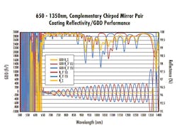
In this case, the microscopist needs to compensate for the GDD of the objective, but does not know the exact specification. They would like to assess image quality as a function of applied negative GDD. This, combined with their broad spectral bandwidth, makes GDD compensation through complementary chirped mirror pairs a good option for the microscopist.
Using mirrors with performance curves like those presented in Figure 4 will provide the microscopist the opportunity to make small incremental changes in GDD by increasing the number of bounces between the two mirrors. When the microscopist achieves optimal image quality, they will have successfully compensated for the GDD applied by the focusing objective. Figure 5 demonstrates the potential optical layout for a chirped mirror pair, denoted as pulse compressing mirrors.
High GDD and flexibility. In this scenario, imagine that you are designing an ultrafast laser system. The laser itself has a certain amount of GDD inherent to its design, and you are unsure how much GDD your end user may need to compensate in their application.
Your laser design has GDD on the order of 104 fs2, and you want tunability over a wide range. This situation could easily arise for a laser engineer who is designing a commercial ultrafast laser system.
In this case, the engineer might opt for the flexibility of a grating compressor. Using two transmissive gratings designed for a particular center wavelength, the engineer can implement a grating compressor system with a variable distance between the gratings. This approach both compensates for the GDD inherent to the laser itself and offers additional flexibility for any additional GDD incurred within the end user’s optical path.
The approaches for GDD compensation in these three examples are not exhaustive but are instead meant to illustrate the various factors to consider when choosing a particular method. From investigating the amount of GDD to determining a compensation strategy, all applications and systems bring unique considerations to the table. For assistance in determining the best approach for your ultrafast application, please reach out to your optical supplier to explore solutions.
REFERENCES
1. See www.laserfocusworld.com/14291054.
3. See www.laserfocusworld.com/14294148.
4. See www.laserfocusworld.com/14292432.
About the Author
Olivia Wheeler
Olivia Wheeler, Ph.D., is an ultrafast laser optics engineer at Edmund Optics (Barrington, NJ).

![FIGURE 3. Example coating performance for a mirror that has been optimized for low GDD. In addition, mirrors for ultrafast laser applications are optimized for high reflectivity and high ultrafast laser damage threshold. See Basics of Ultrafast Lasers series, Part 2 for more information; www.laserfocusworld.com/14292432. [4] FIGURE 3. Example coating performance for a mirror that has been optimized for low GDD. In addition, mirrors for ultrafast laser applications are optimized for high reflectivity and high ultrafast laser damage threshold. See Basics of Ultrafast Lasers series, Part 2 for more information; www.laserfocusworld.com/14292432. [4]](https://img.laserfocusworld.com/files/base/ebm/lfw/image/2024/10/670821fdf141fc1df835b6af-2501lfw_whe_3.png?auto=format,compress&fit=max&q=45?w=250&width=250)
