Small-diameter optical fibers are enabling leading-edge biomedical applications, including optogenetics, two-photon microscopy, and vitreoretinal surgery. But efficient coupling of light into these small-diameter fibers necessitates a new type of light source. With effective optical design, laser diodes can fill this role—not only in biomedicine and life sciences, but in many other applications as well.
Conventional fiber-optic illumination
A typical fiber-optic illumination system consists of a primary or secondary light source (see “Primary and secondary light sources”), a fiber-optic receptacle, an optical system in between, and a mechanical housing with passive or active cooling and electronics.
The main optical parameters of a light source are emitter size, angular intensity distribution, and emission spectrum profile. Other important parameters are warm-up time, possibility of direct modulation, wall-plug efficiency, lifetime, and eye safety.
Large emitters require large lenses to achieve good collimation, and are inefficient for illuminating small areas, including small-diameter optical fibers. It can be said that progress in light sources is directly related to the shrinking size of the emitter area and decreased angular intensity distribution. Historically, there was a candle, the Edison light bulb, the sodium lamp, lamps in the 2–3 cm range (such as xenon), LEDs in the 1 × 1 mm range, and laser diodes in 1 × 5 µm range. Despite being a key parameter for light sources, emitter size often goes unreported or unspecified by manufacturers.Angular intensity distribution is also referred to as far-field emission pattern, polar radiation pattern, or far-field intensity distribution. Older light sources such as candles and light bulbs feature omnidirectional angular intensity light distribution. Newer sources such as LEDs and laser diodes have more restricted far-field emission patterns. A smaller angular intensity distribution spread makes it easier for optics to capture more of the light for collimation or focusing. For first-order optical simulation, it is enough to consider full-width half-maximum (FWHM) spread of the angular intensity distribution. The FWHM angular spread is used extensively by laser diode manufacturers. By comparison, angular intensity distribution of other primary light sources having more complex shapes is more difficult to represent and to make full use of it.
Incandescent bulbs and other lamps provide broad-bandwidth spectra that can have widely diverse spectral profiles, or spectral power distribution. LEDs have narrow bandwidths of roughly 50 nm FWHM around peak emission wavelength, while laser diodes have very narrow emission bandwidths of just a few nanometers.
Optically relevant parameters of a receptacle include size, acceptance angle, and reflectivity. The receptacle can consist of the single optical fiber, the fiber-optic bundle, or the liquid light guide. Receptacle diameter can be as small as few microns for single-mode optical fiber, a few hundreds of microns for multimode fibers, a few millimeters for fiber-optic bundles, and typically 5 mm for liquid light guides.
With the exception of single-mode fibers, acceptance angle is typically >60°. The reflectivity of the receptacle surface without antireflection coating increases with incidence angle, except for p-polarized light under Brewster angle of incidence when the light is totally transmitted.Tradeoffs in fiber-optic systems
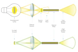
The Lagrange invariant states that the product of the emitter size and its angular intensity spread (étendue) remains constant from the light-emitting surface to the image surface of an optical system. If a light source has larger étendue than the receptor, a portion of emitted light is inevitably lost. Reducing emitter size by the magnification of the optical system increases angular spread and vice versa. Unfortunately, the emitter size and étendue of traditional light sources are much bigger than those of small-diameter optical fibers with limited numerical aperture (see Fig. 1).
Fiber-optic illumination systems with traditional lamps are inefficient and bulky, have complex optics and filters, and are suitable only for larger-diameter optical fibers or liquid light guides. More-efficient coupling of light into small-diameter optical fibers requires a new type of primary or secondary light source with smaller étendue, or at least smaller emitter size.
The use of specific-color LEDs in illumination systems with larger-diameter optical fibers represents an improvement over traditional sources due to their relatively small emitters and ease of modulation, among other things. However, these LEDs are not very bright, and their coupling into small-diameter optical fibers is inefficient. In addition, they offer a limited choice of wavelengths.
Gallium nitride LEDs with fluorescent over-layer provide spectrally broader “white” light illumination. Nevertheless, they are not suitable for coupling into small-diameter fibers for the same reasons as LEDs of color.
Laser diodes have relatively small étendue with small emitters (thickness of ~1 µm; length from a few to hundreds of microns) and beam divergence of up to 70° in the “fast axis” direction of the wave plate, but only a dozen degrees in “slow axis” direction. They can support 100–1000X higher optical power than blue LEDs. There are several practical solutions for coupling laser diodes, laser diode bars, and arrays of laser diode bars into small-diameter fibers that produce bright sources of coherent light. Speckle, narrow spectral bandwidth, and limited choice of wavelengths are drawbacks.Efficiency with a secondary source
A truly efficient fiber-optic illumination system needs a secondary light source with a small étendue (or at least a small-area emitter), high brightness, and wide optical spectrum. This type of source can be built with blue laser diodes having relatively small étendue and high brightness—the laser diodes are collimated and, under different incidence angles, focused to a small spot on the fluorescent crystal, where the light is converted into the wide spectral bandwidth fluorescent light. A well-known application of this approach is the BMW i8 headlight design, where a portion of blue light is turned into fluorescent light and mixed with remaining blue light to synthesize white light.
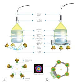
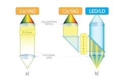
In Doric Lenses’ approach, the p-polarized light from several blue laser diodes is directed under the Brewster angle onto the cerium-doped yttrium aluminum garnet (Ce:YAG) crystal without reflection losses (U.S. Patent 9,933,605 B2), where laser beams are overlapped within a well-defined small area on the crystal. The first version of this source used five laser diodes, and collimation and focusing optics were positioned along the Brewster angle direction (see Fig. 2a).
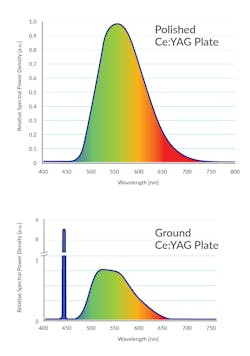
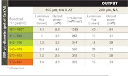
For the sake of compactness, easier assembly and thermal management, a later version of this light source has several laser diodes radially positioned within the same plane. Their outputs are collimated parallel to each other and brought to the 300-µm-diameter spot on the fluorescent crystal with a parabola (see Fig. 2b). In this configuration (U.S. Patent 10,094,536 B1), the fluorescent crystal and the laser diodes have a common heat sink. The 300-µm-diameter spot on the crystal becomes a secondary light source with broad spectrum, perfect for coupling into 200-µm-diameter fiber, de facto standard light delivery optical fiber for optogenetics and miniature fluorescence microscopy. When the top surface of the crystal is well polished, it emits only fluorescence light (480–650 nm), while the mildly ground surface provides the mix of the fluorescent and scattered blue light perceived as a white light (see Fig. 3). Other crystals and spot sizes can be used if adequate cooling is provided. The table shows output power, irradiance, and luminous flux specifications of this source.
The Ce:YAG source is being offered as a fiber-coupled module, a collimated module, a connectorized Ce:YAG light source, and a connectorized Ce:YAG light source combined with blue LED or laser diode. The last two sources come with an interchangeable filter set and a driver (see Fig. 4).Applications
The Ce:YAG light source was initially developed to deliver the amber light via a 200 µm optical fiber to halorhodopsin-tagged neurons in optogenetics experiments focused on activity silencing. It can also deliver any section of the spectrum from 480 to 650 nm that might be needed for opsin activation or fluorescence excitation—as in miniature optogenetically synchronized and two-color fluorescence microscopy systems (offered by Doric Lenses). Unlike some solid-state lasers, the Ce:YAG source can be electronically modulated.
For endo-illumination in vitreoretinal surgeries, the Ce:YAG source can provide broadband visible light without the blue wavelengths that are potentially hazardous to the retina. If some blue light is needed to improve contrast and visibility inside the eye, it can be added as a separate, controllable LED or LD channel.
Another benefit is that smaller 27 Ga cannulas, fitted with 200-µm-diameter optical fibers, can be inserted and removed from the eye with less potential for damage. And while the coupling of conventional light bulbs into 200 µm fibers is challenging at best, it is straightforward for a Ce:YAG light source.
White-light illumination is appealing to system designers and users alike for dental headlamps, operating room illuminators, and other medical and nonmedical applications needing low-divergence light beams. In modern endoscopy, illumination delivered via small-diameter optical fiber is sought-after because it yields brighter images and leaves more space for other surgical instruments than larger-diameter fiber.
Primary and secondary light sources
The term light source is commonly used to refer to both complex illumination systems and simple light sources such as lamps, LEDs, or laser diodes. To remove this ambiguity, we introduce the notion of a primary light source (to describe a source such as an incandescent light bulb, mercury lamp, halide lamp, high-intensity discharge [HID] lamp, fluorescent lamp, monochromatic LED, laser diode, or gas laser) and a secondary light source, which transforms light from a primary source in any of various ways, most notably wavelength range (as with crystal and fiber lasers).
This concept is well illustrated by white LEDs, in which the primary source is a blue LED that irradiates a phosphor coating. The coating converts a large portion of received light into its fluorescence spectrum that—with residual unconverted blue light—makes up so-called white light. Because its light is created through interaction of blue light with the phosphor, the white-light LED is considered a secondary source.
Sead Doric | CEO, Doric Lenses
Sead Doric, Ph.D., is CEO of Doric Lenses (Québec City, QC, Canada).
