Designing and analyzing automotive head-up displays
Contemporary automotive market demand has led to a wealth of new applications requiring strong performance in cost-effective optical systems. Requirements for these systems require modern software capability for both optical design and engineering. This article presents a discussion of optical design and analysis for a quality automotive head-up display (HUD) system using Lambda Research Corporation’s Optics Software for Layout and Optimization (OSLO) and TracePro. These products are designed to work in tandem to effectively solve a wide array of problems in optics.
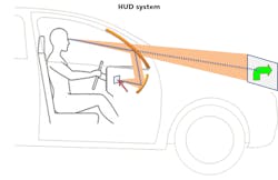
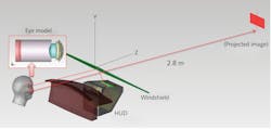
HUD systems are transparent displays providing information and data in the normal viewpoint of the user. Normal viewpoint essentially means that the user has augmented data displayed that they can view without needing to rotate their eyes or head, which is a key current safety feature in automobiles. Even with the advent of self-driving cars, demand for augmenting systems is likely to persist. The system concept used for this article is shown in Figure 1.
The high-level concept is that a self-luminous source panel projects data that is then viewed as a virtual image by the user. Successful implementation of HUD systems conveys the desired information to the user, provides good image quality including contrast, suppresses unwanted artifacts such as double images, helps the user with diagnostic information, and maintains great illumination properties for use in a wide variety of conditions. These systems must operate under a variety of use conditions and be cost-effective. Requirements include not only imaging performance, but also view-condition-specific illumination features.
Industrial design an important factor
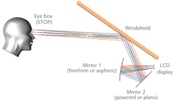
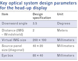
A further insightful view of the system concept is shown in Figure 2, where typical components are illustrated. The source display illuminates a reflective system with powered optic(s) that have some of the light reflecting off the windshield into the eye box for the viewer. There are different concepts possible in implementation, but the most common current configurations include two reflectors. Many manufacturers further consider the industrial design to appeal to the customer base as a very important feature of the design work. It is very important to provide information feedback on these industrial design factors to enable success.Imaging performance has been optimized taking full advantage of the design flexibility and freedom provided by OSLO. OSLO has coordinate capability and constraining to manage off-axis reflective designs such as this design, as well as challenging reflective telescopes, in large part due to its flexible coordinate system implementation. Here, a combination of decentrations, surface tilts, and coordinate returns has been used to design and analyze the system. OSLO slider controls are of great help in this type of system and were also used to help with the initial optical layout. OSLO’s operand error function format using a spot diagram metric was implemented to further optimize the system to achieve diffraction-limited performance for the use conditions.
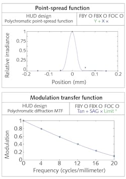
Going back and forth between these modeling options is certainly possible and allows designers the flexibility to efficiently design for numerous different specifications. Many analysis features to analyze spots, distortion, modulation transfer function (MTF), and extended source simulation were also incorporated into the work. The system performance is shown for a subset of these metrics in Figure 3, which includes the double image analysis work done in TracePro.This type of HUD system poses several challenges that go beyond the imaging performance. The design process took advantage of the solid modeling, source modeling, surface properties, forward raytracing, luminance analysis, and photorealistic rendering in TracePro to manage these additional factors. Changing properties for sources and surfaces in TracePro can be done using its database of properties or building the data required and storing it as general surface properties. The database capability within TracePro facilitates different sources and surface design features to ensure performance.
Modeling double imaging in TracePro
Concurrent engineering work can be done in OSLO and TracePro as required. For example, if the windshield is modeled as a reflector vs. a window, the designer misses the problem that reflections off the front and back surface of the window can cause double imaging. This problem can easily be modeled in TracePro after transporting the system data and building the source and solid model geometry required. To manage this double-image issue, it is very important to design the windshield with a taper. In our example design, the tapering of the window has been modeled with two different configurations in OSLO and optimized to make the reflections off both surfaces coincident. Doing this work in OSLO helps maintain imaging performance for the wedged window throughout the entire eye box and field of view for the user.Design of HUD systems must correctly incorporate several factors for imaging and illumination performance. This example design process takes advantage of the flexibility of both OSLO and TracePro, including portability between the packages, to successfully design an effective HUD system that can be used in current and future automotive production models. The marketplace will continue to include more of these types of systems as the automotive market continues to advance. Careful analysis of these systems should include luminance factors, double imaging, and optical system performance.
Chihyun Chan
Chihyun Chan is with Lambda Research Corporation (Littleton, MA).
Chao-hsi Tsao
Chao-hsi Tsao is with Lambda Research Corporation (Littleton, MA).

Dr. Richard N. Youngworth | Chief Engineer
Dr. Richard N. Youngworth is an experienced optical engineer and the Chief Engineer of Riyo LLC, an optical design and engineering services company based in the United States.
