Optical multilayer devices consist of a sequence of thin layers, typically just two transparent materials. They can perform a wide range of optical functions, including antireflection properties, wavelength filtering, and light separation based on polarization. Such functions are achieved by choosing an appropriate design; i.e., a suitable sequence of layer thickness values.
A challenge is often finding a working design, or even evaluating whether a design meeting the requirements of a specific application may exist. Very different design methods can be appropriate, depending on the type of required optical functions. In any case, we assume a sufficiently powerful multilayer optics design software is used. In addition to suitable software, a good idea for an appropriate design strategy is helpful. Generally, one should not expect that powerful software will automatically deliver good designs for every conceivable purpose.
What are the design goals?
Before starting any automated design optimization process, it is necessary to precisely define the required optical properties. More generally, it is necessary to provide a way for the software to determine how close to ideal performance different designs are. Only then will it have a chance to find designs that will work well.
The commonly chosen method is to define a so-called figure-of-merit (FOM) function. This is a function that provides a single value, which is supposed to be a reasonable measure for how close it is to an ideal design. A common way is to define the function so that it would deliver a zero result in the ideal case, and positive values for less satisfactory designs. There will often be multiple criteria, which may all add positive penalty points to the result. For example, an FOM function may have the following form, if only reflectance values at various wavelengths are of interest:
Simple software will often use a built-in FOM function of a fixed structure, where only parameters can be adjusted by the user. The user may enter multiple wavelengths and the corresponding desired reflectance values, for instance, and the software may calculate the sum of the squares of deviations from those reflectance values.
For higher flexibility, software may offer multiple versions of FOM functions. However, it is much better if it allows the user to freely define any kind of FOM function by entering a mathematical expression. This can refer to any possibly relevant optical properties of a structure: not only reflectance or transmittance, but also wavelength-dependent group delay or group delay dispersion, and all this for any angle of incidence, polarization, and wavelength. It allows the implementation of a huge number of ideas. For example, differences in reflectance at different wavelengths could be used if relative wavelength independence within some range is more important than the absolute values.
Antireflection coatings
A typical task is to design an antireflection coating that works within a certain wavelength range, or possibly within multiple ranges. While the function of simple single-layer coatings is easy to understand, complicated interference effects are relevant for multilayer coatings. Still, the task is relatively easy with suitable software. Since only a small number of layers are required, a brute-force approach could be taken—trying to find a numerical solution by trial and error, without any physical understanding of how exactly the design should work.
Often, it will not be sufficient to start with a random multilayer sequence and improve performance by local numerical optimization, trying to get the FOM value down as much as possible. This is because we are operating in a multi-dimensional space (with one dimension for each layer), in which the FOM function has a huge number of local optima. Local optimization easily gets stuck at one of those, which tends to be far from good enough. Typically, that problem is solved with a Monte-Carlo approach: we try a large number of combinations of random layer thickness values, take a subset of those with reasonably low FOM, and locally optimize them further. An ordinary office PC with suitable design software is normally sufficient for finding a solution within a reasonable amount of time, for example within less than one minute.
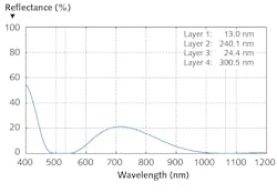
Figure 1 shows the reflectance vs. wavelength of a sample design found within a couple of seconds with the RP Coating software on an old PC. The target was to reach small reflectance at both 532 nm and 1064 nm. The FOM used contained reflectance penalties within a range around each wavelength.
Before using such a design, it is necessary to also evaluate its sensitivity to layer thickness errors. For example, we may assume either systematic errors for all layers, or a set of design versions with random errors for each layer separately. That may be integrated into a second version of FOM, just for checking whether the solution found is overly sensitive.
Dichroic mirrors
For some lasers, dichroic mirrors are required where one has a high reflectance (>99.9%) at the laser wavelength and at the same time high transmittance at a shorter wavelength of pump radiation. Such a device requires substantially more layers to reach the high reflectance. As a result, the number of dimensions is usually too high for a brute-force computational approach.
A simple design idea would be to use a Bragg mirror (containing only λ/4 layers) so that the laser wavelength is within the Bragg reflection band while the pump wavelength sits outside, ideally between the side lobes in the properly positioned reflectance spectrum. For substantially better performance, simple modifications are known, in which one uses λ/8 layers at the start and end. Performance can be further improved by numerically optimizing all thickness values for an even lower FOM.
To implement such a strategy, the software should allow the user to conveniently define the initial design—not by manually entering externally calculated thickness values, but so that the thickness values are automatically calculated based on a few entered parameters. Then, it is convenient to try with different numbers of layer pairs, different coating materials, etc.
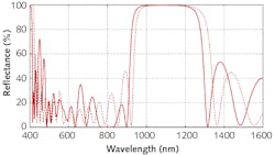
Figure 2 shows an example design for a laser wavelength of 1064 nm and a pump wavelength of 808 nm, as is common for Nd:YAG lasers. The dashed curve shows the initial design, while the thicker solid curve shows the numerically optimized design. Since only a single local optimization is required, the computation is done within a couple of seconds.Double-chirped mirrors
Rather sophisticated design tasks arise when mirrors with controlled chromatic dispersion properties are required. This is particularly difficult when precise dispersion properties are required within a substantial spectral range, as is the case for broadband mode-locked lasers. For such applications, so-called double-chirped mirror designs were proposed by Franz Kärtner in 1997.1 In contrast to an ordinary Bragg mirror, the Bragg wavelength is systematically increased in one direction; in a simplified picture, the resulting chromatic dispersion arises from a frequency-dependent penetration depth within the structure. In addition, one needs to vary the relative thickness for the two materials and also place a broadband antireflection structure on top (unless opting for a design used under Brewster’s angle).With sufficiently flexible design software, the design process can start with an initial design, composed from a parametrized mirror structure (controlled with a couple of design parameters) and a previously optimized antireflection structure. In a first step, one can efficiently optimize the double-chirped structure through the mentioned moderate number of design parameters. This can be followed by a further local optimization, which can adjust all layer thickness values independently.
Conclusions
Rather different design strategies must be used, depending on the type of optical device to be designed. Particularly for antireflection structures, a brute-force numerical approach works well, whereas in cases requiring many more layers, there should be a reasonable initial design. Successful design work requires sufficiently flexible software, which allows the user to freely define merit functions for design goals and initial designs. Suitable ideas are also required for design strategies, which may come from previous experience, from examples delivered with the software, or from competent technical support from the software provider. On the other hand, the requirements concerning computing power are then quite modest; an ordinary office PC is usually sufficient.
REFERENCE
1. F. X. Kärtner et al., Opt. Lett., 22, 11, 831 (1997); doi:10.1364/ol.22.000831.
About the Author
Dr. Rüdiger Paschotta
Founder and Managing Director, RP Photonics Consulting
Dr. Rüdiger Paschotta has done a Ph.D. and a habilitation in physics. He is author or coauthor of more than 100 articles in scientific journals, and of several books and book chapters. His best known publication is the online Encyclopedia of Laser Physics and Technology. He is also well known as a course instructor at conferences.
In 2004, he founded the company RP Photonics Consulting, offering technical consultancy, staff training courses, and simulation and design software for fiber optics, lasers, ultrashort pulse generation, and multilayer optics.


