How to select beam steering technology
Beam steering is a critical part of many high-performance photonics instruments and systems for medical, industrial, defense, and consumer markets. Precise management of light paths is an essential function of optical assemblies embedded in these instruments. These optical assemblies actively optimize beam quality, alignment, focus, and other critical parameters.
Understanding how to select the best beam steering solution for your product during your development cycle will ensure you come away with optimal performance requirements, including size, weight, power, speed, and range of motion. Here’s what to look for as you compare several different MEMS, micro gimbal, and galvanometer systems with respect to these requirements.
Let’s look at a range of products outside of resonant mode scanners and shorter-range fast steering mirrors capable of providing two-axis beam steering (orthogonal tip and tilt) with greater than four degrees of mechanical rotation and precise point-to-point positioning.
The products are evaluated for performance parameters, including:
- Size and properties of mirror(s)
- Range of mirror motion (orthogonal tip and tilt)
- Time to move and settle
- Stepping precision
- Integration of electronics and sensors
- Total system size
- System voltage and power to move and hold position.
MEMS mirrors
Micro-electromechanical systems (MEMS) devices are defined by one-piece construction that uses the silicon microfabrication method. Complex one-part MEMS mirror assemblies integrate a single mirror, actuators, and guide mechanisms. MEMS devices are generally viewed as potentially lower cost at large production quantities versus the other solutions mentioned herein. Yet, they do not necessarily offer the smallest size. Consider MEMS mirror systems using two different forces for motion: Electrostatic and electromagnetic.
MEMS electrostatic actuators. MEMS electrostatic actuators use electrostatic attraction and repulsion to generate mirror movement. Mirror rotation is a non-linear function of input voltage and must be calibrated. Drive and control electronics are separate from the MEMS device.
MEMS electromagnetic actuators. MEMS electromagnetic actuators use coils and separate magnets to generate Lorentz forces that rotate the mirror. This type of actuator is also called a voice coil motor (VCM). Input current generates a force that linearly deflects torsion springs and rotates the mirror. Mirror rotation is a function of input current and must be calibrated. Drive and control electronics are separate.
Micro gimbal assemblies
A micro gimbal assembly uses discrete components to create a two-axis rotation (tip/tilt) of a single mirror. Here, we consider two types of micro gimbal mirror actuators: piezo motor and VCM.
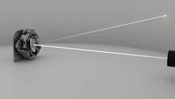
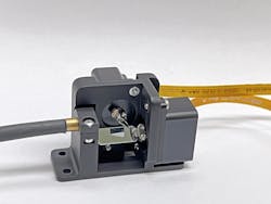
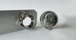
Micro gimbal with piezoelectric ultrasonic motors. This micro gimbal system uses tiny piezoelectric ultrasonic motors to generate orthogonal mirror rotations (see Fig. 1). These direct-drive motors generate linear tangential forces that rotate the orthogonal axes, and they can hold any angle position with zero power using static friction. Integrated position sensors enable closed-loop control. Drive and control electronics are integrated with the mirror assembly.
Micro gimbal with voice coil actuators (VCMs). A micro gimbal with VCM uses electromagnetic (Lorentz) forces from coils and magnets to generate orthogonal mirror rotations. Zero current produces zero force and moves the mirror to the center point of the flexure guides. Integrated position sensors enable closed-loop control. Drive and control electronics are separate.
Micro galvanometer assemblies
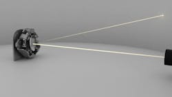
A two-axis galvanometer mirror assembly uses two independent rotary actuators to move two orthogonal mirrors (see Fig. 2). We consider two types of galvanometers: One using piezoelectric motors and another using traditional VCM drives.
Micro galvo with piezo motor drive. This assembly has two independent piezo motor rotary stages with orthogonal rotational axes, following the architecture of conventional galvo scanners. The piezo motors generate tangential forces that rotate the mirror on each stage and hold position with zero power. The beam path reflects from the mirror surfaces for two-axis beam steering. Angle sensors and electronics are integrated into each rotary module, so no external controller is needed.
Standard galvo scanner with VCM drive. The conventional large galvo scanner design combines two independent electromagnetic rotary modules (VCMs) moving two orthogonal mirrors. The beam path reflects from two orthogonal mirrors to produce two-axis beam steering. Angle sensors are integrated. Drive and control electronics are separate.
Selecting a beam steering system
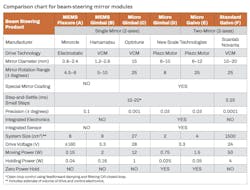
While many beam steering technologies are available, the examples presented here are commonly used within the photonics space, particularly for applications with demanding precision, speed, and power requirements. The table provides a detailed technical comparison of the examples presented. Consider these points as you evaluate your photonic system requirements.
Mirror properties: Diameter and reflectivity. Consider your beam size, range of motion, wavelength, and optical power. These parameters define the required minimum mirror diameter and reflectivity.
MEMS mirrors are the smallest in diameter (typically 1 to 3 mm) and are limited to metal coatings with modest (~90%) reflectivity. Options for higher reflectivity (>99%) dielectric coatings are challenging to integrate with silicon microfabrication.
Micro gimbal mirrors and galvos are larger (5 to 20 mm) and use discrete, separable mirrors that are easily customized for substrate material and coating.
Range: Many good options. Consider your beam range of motion (orthogonal tip and tilt) and remember that the beam reflected angle is twice the mirror angle. MEMS mirrors typically have the smallest range of movement (up to ±10 degrees) due to the limits of the silicon structures. Micro gimbals and galvos have greater ranges (up to ±25 degrees). For many applications, mirror movement of ±10 degrees is more than sufficient, and angles greater than ±25 degrees may create optical challenges due to lower angle reflections and larger lateral beam shifts.
Speed: Larger is faster. The clear winner for speed is the conventional VCM galvo, which is the largest system and uses the most power. This result may surprise some, who expect that smaller means faster. In this case, the high torque and speed of conventional galvos, along with their high resonant frequency, provide settling times at least 10 times faster (<0.25 ms) than the other examples.
Precision: Bigger is better. Again, the clear winner is the conventional galvo, which is also the largest system. Stepping precision is determined by the resolution of the angle sensors. Larger diameter sensors have a larger radius of measurement, and therefore, the greatest angular sensitivity. A conventional galvo has 10 to 100 times better precision (0.0001 degrees) than the smaller system examples.
Integration: Built-in control electronics save space and time. Mechatronic integration of electronics and sensors, together with the actuator, into a complete motion system is the key to reducing the total size and mass of beam steering and photonic systems. The piezo motor options, for both micro gimbal and galvo, integrate sensors and smart drive and control electronics into one mechatronic system. The only inputs are 3.3 VDC power and digital comments. This system architecture dramatically reduces cables and connectors and creates a plug-and-play solution that is the easiest to integrate into photonics products. Separate electronics require more space and prolong the development time.
System size: MEMS is not the smallest. Mechatronics integration reduces the volume of the piezo motor micro gimbal system (~2 cm3; see Fig. 3) and galvo system (~4 cm3) and provides the smallest system size. MEMS systems are modestly larger (~8 cm3), while the conventional galvo is 750 times larger (1500 cm3).
While MEMS components are very small, the peripheral items and electronics required to create a system are relatively large. Miniaturization of higher voltage drives electronics and connections can also be challenging.
System power: Moving and holding. Moving power and holding power must be considered together to pick the best solution for your use case. When moves are infrequent, holding power dominates. When moves are more frequent, moving power is most important. In these examples, the choices for power span a factor of more than 300.
The winner for moving power is the MEMS electrostatic mirror, with a moving power of only 150 mW. The piezo motor examples require 5 to 10 times more moving power (150 to 1500 mW). The smaller VCM options move with 2 to 12 W, while the conventional galvo requires 50 W.
The winner for holding power is the piezo motor, which holds with static friction using zero power. This is achieved by turning off the electronics. If the electronics must remain active, the quiescent power is 10s of milliwatts for both piezo motors and MEMS electrostatic mirrors.
Which beam steering solution fits your project?
It’s important to understand the fundamental tradeoffs when considering the best solution for a project. The best precision and speed are achieved with large conventional two-mirror galvanometers. Optimum size, weight, and power (SWaP) are achieved with piezo systems with embedded electronics.
MEMS systems may not be practical for highly customized applications. However, MEMS systems may provide the lowest-cost option for very high-volume manufacturing.
The piezo motor beam steering systems described above are mechatronic all-in-one solutions, designed for use as embedded motion systems in photonic instruments. These innovations enable the smallest system size, easiest integration, and fastest development times.
Embedded beam steering solutions keep pace with parallel photonics innovations in detectors, sources, processing power, imaging, biology, quantum devices, and micro-optics. When combined with next-generation photonics instruments, new capabilities include smaller, more closely packed light and sample channels to increase throughput; more sensitive and faster detectors that gather more data with greater signal-to-noise precision; embedded computer processing and memory for near-sensor digitization and data processing; reduced sample sizes; reduced power and heat; and robust active alignment over a wider range of environments.
About the Author
David Henderson
Founder & CEO, New Scale Technologies
David Henderson is a technology innovator, experienced business leader, and proven team builder. He has more than 35 years of experience in engineering, new product introduction, worldwide market development, and profitable business operations. David’s technical expertise is mechanical and precision systems engineering. He has published or presented numerous papers and has been awarded more than 20 patents, including patents for the SQUIGGLE at UTAF piezoelectric motors.
Before founding New Scale in 2002, David was director of the positioning product division of Burleigh Instruments (now EXFO), where he achieved 300% revenue growth with 20% EBITA from 1994 to 2000. He has prior experience as a program manager and mechanical engineer with Contraves USA.
David has a BS in Mechanical Engineering and MBA from Carnegie Mellon University. He serves as chairman of the New Scale Technology board of directors.
