VIBRATION-CONTROL SYSTEMS: Table improves optical systems from the ground up
Photolithography and the semiconductor industry are facing a critical juncture. The 32 nm node (at which production photolithographic technology is able to pattern some specific chip features at 32 nm) is only a few years away, and next-generation methods for patterning the even-smaller, sub-30-nanometer-scale dimensions on silicon wafers at the node beyond that are unproved. Scientists at IBM’s Almaden Research Center (San Jose, CA) aimed to explore this territory with IBM’s “NEMO” interference immersion-lithography test apparatus, but to push the limits of optical imaging, the apparatus had to be in an exquisitely stable environment.
In early 2006, IBM was among five recipients of the first of a new type of intelligent-damping (iQ) optical table developed at Newport. The table provided to support NEMO included traditional pneumatic floor isolation, as well as closed-loop active damping for flexural stability. The results are just coming in, but they support recent findings that iQ technology cost-effectively improves vibration damping by a factor of 10 across low, medium, and high frequencies by up to 22 dB compared to traditional passive-damping technologies, making new levels of optical alignment, imaging, design, and measurement available to a far greater number of laboratories.
Damping down
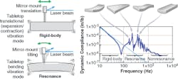
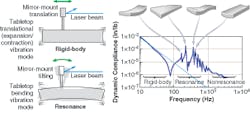
The creation of the active vibration-control platform called the SmartTable began with an analysis of the dynamic properties of optical tables, which are usually characterized by their dynamic compliances. Dynamic compliance is the ratio of dynamic deflection to dynamic force, as a function of frequency. For a free rigid body, dynamic compliance is inversely proportional to frequency squared, as represented by a straight line on a logarithmic scale. Plots of dynamic compliances provide a convenient way to estimate deviations from rigid-body behavior, and recent reports show that optical-table designs are influenced by three separate frequency bands (low, medium, and high) ranging up to a few kilohertz.
Optical tables use pneumatic cells inside the table legs in combination with the table’s materials and design to reduce high-amplitude, low-frequency vibrations, typically caused by objects in the environment (people walking, building equipment, passing automobiles, and so on). These external forces create rigid-body motion, which is essentially two-dimensional, and does not affect most optical experiments. High-frequency vibration sources in the kilohertz range do not greatly affect table stability; however, medium-frequency resonance and flexural vibrations-resulting in the bending of an optical table’s surface-can greatly affect optical alignment (see Fig. 1).
Resonances in the form of flexural vibrations are typically caused by loads on the table’s surface and/or environmental disturbances and typically exist between 100 and 500 Hz. These vibrations can be controlled in two ways: tuning the table through the use of heavy tuned or broadband damping cells, or through the use of active damping to counteract the existing flexural frequencies. Until recently, both tuned and broadband approaches were the only feasible approaches to damp resonant frequencies in optical tables. One problem with these solutions is that frequency bands change as the load on the table changes; another is that a subsequent experiment may require a different (and uncompensated) tuning region. A better solution is to build a table that can sense existing vibration frequencies in real time and actively damp them without introducing instability in the table.
Intelligent damping (iQ)
The SmartTable series of optical tables begins with a traditional optical-table design, but to achieve active damping, the table is equipped with two iQ dampers. When the dampers are connected to iQ control electronics, the table’s resonance frequencies are determined by the electronics, which engage the dampers to eliminate harmful table resonances between 100 and 500 Hz with a high dynamic range (on the order of 106). This wide dynamic range results in suitability for a wide range of real-life vibration environments, from submicron-per-second compensation in quiet laboratories to fractions of millimeters per second (root-mean-square) in semiconductor-production facilities.
Active damping must be carefully controlled to make sure the feedback does not result in an unstable system (similar to placing a microphone too close to a speaker), while still achieving maximum damping. Initially, analog signals from each embedded sensor are passed along separate channels to preamplifiers and bandpass filters to condition the sensor output signal before feeding it to the digital controller. The controller implements recursive filters that compensate for the dynamic response of the actuator and correct the phase to bring the phase difference between the displacement and force close to -π/2 in the desired frequency range. This, in effect, emulates the action of a viscous damper in the frequency range of interest.
The control functions include gain factors k1 and k2 that define the tradeoffs between damping performance and system stability (see Fig. 2). It is desirable to make these gains as high as possible to maximize the damping and thereby decrease the vibration level; however, the feedback system would become unstable if the gains were too high. Optimal gain values depend on the payload configuration. Analytical determination of the optimal gains for a given stability margin would require a full model of the plant (table and payload) and control circuitry. This is not practical. Even if such models were available, the optimum tuning of k1 and k2 would change because of variation in sensitivities and motor constants of sensors and actuators, in addition to variations in the parameters of mechanical and electronic components.
To circumvent this problem, a simple method is used to adaptively tune the control-loop gains. The procedure consists of the following steps. Initially, the first control channel is enabled and the second one is disabled. The first-channel gain is ramped up until the onset of instability is detected by the controller. After that, the gain is scaled back to stay in the stability domain. A converging search by bisection is used to make the procedure more precise. The value of the gain is stored. The procedure is then repeated for the second channel. Finally, both channels are enabled and the gains are ramped up proportionally to the stored values until instability is detected by at least one channel. After that, all the gains are scaled back in small proportional steps to stay in the stability domain.
Again, bisection is used to make the procedure more precise. A safety factor is applied to the resulting gain values. The control law emulating the action of a viscous damper in the frequency band of interest is implemented by a broadband filter in the feedback loop. The feedback gains are restricted by the stability requirements as described above. The second part of the auto-tuning procedure serves to increase the efficiency and reduce the side effects of signal filtering by using, in parallel, additional narrowband filters in the vicinities of the main resonance frequencies. These narrowband filters emulate the action of tuned vibration absorbers. The controller finds the natural frequencies by analyzing the system response to random vibration. The gains associated with narrowband filters are adjusted by the ramp-up procedure similar to that described above. The whole auto-tuning process is conducted automatically by the control firmware and is completed within seconds.
Auto-ranging
To maintain a high signal-to-noise ratio, the SmartTable control system uses auto-ranging based on the mean-square value of the feedback signal. The switching of preamplifier gains is accomplished by driving a signal that sets up the preamplifier at a desired level. The switch is done in a way that does not change the signal parameters of noise, phase, and bandwidth-only the gain is changed. The low-noise preamplifier is essential to ensure a high electrical signal-to-noise ratio. If the feedback signal is at the lowest gain and still violates the desired constraints, the system is said to be in a “vibration overload” condition. The overload condition is also detected using an error signal that is generated by the signal clipping detectors in the preamplifier. The overload condition is reported to the user. The system is, however, capable of operating in overload condition although perhaps not with the same efficiency.
An additional benefit of the frequency sensing at the heart of the SmartTable iQ system is that the controller unit can communicate via USB interface with a PC to display the table’s vibrational condition across time and frequency, potentially providing additional experimental information on the optical system. Software supplied with the system allows users to change the controller settings, and also collect, display, and store vibration data in time and frequency formats.
The real-time damping capabilities of optical tables with adaptive tuning provide better stability with less weight and cost-in addition to providing table frequency monitoring and data-collection capabilities-than custom-made tuned systems.
Case study: Immersion lithography
In the chip-making industry, fabricating a typical computer processor or memory chip can require dozens of photolithography cycles consisting of photoresist exposure (in which projection optics image the chip pattern onto the wafer), development, etching, and deposition. Over the years, the industry has moved to smaller circuit features-which typically lead to smaller, faster, and cheaper electronics-by using ever-shorter wavelengths of light, lenses with higher numerical aperture (NA), and, most recently, inserting a liquid between the final lens and the silicon wafer, allowing the NA to be boosted even further.
Until now, it was not known whether the industry could continue to adapt this optical-immersion technique to produce sharp features smaller than 32 nm. Plans are being explored for switching to a radically different, unproven, and much more expensive manufacturing method that uses soft x-rays (also known as EUV, for extreme-ultraviolet light) and exotic mirrors, rather than laser light and lenses. The insertion point for this technology is uncertain and the industry needs to extend current optical-lithography techniques as far as possible.
To explore the theoretical limits of 193 nm optical-immersion lithography, IBM developed NEMO (see “Optical immersion further shrinks feature sizes,” www.laserfocusworld.com/articles/252478). This tool uses two intersecting laser beams to create interference patterns with spacings closer than can be made with current chip-making apparatus. The SmartTable vibration-control system that helps NEMO deliver its state-of-the-art results senses low, medium, and high vibrations generated by environmental conditions, as well as by the experiment itself. The table uses actuators to actively cancel those vibrations (in a similar manner to adaptive-optics systems, in which closed-loop feedback is combined with an array of mirror actuators to maintain an unaberrated optical wavefront).
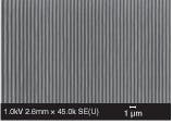
Experimental images obtained by Robert Allen, manager of lithography materials at IBM’s Almaden Research Center, and his associates may be helping to rewrite predictions concerning the future of optical lithography; the NEMO photolithography system generated uniformly spaced lines less than 30 nm wide, less than one-third of the semiconductor industries existing microlithography production capability (see Fig. 3). “Our goal is to push optical lithography as far as we can so the industry does not have to move to any expensive alternatives until absolutely necessary,” said Allen. “This result is the strongest evidence to date that the industry may have some breathing room before any radical changes in chip-making techniques will be needed.”
Now that a path for extending optical lithography has been demonstrated, high-index lens materials must be developed to enable its commercial viability. In the NEMO experiments, the lens and fluid both had a refractive index of about 1.6, while the index of the photoresist was 1.7. Future research is aimed at developing lens, fluid, and photoresist materials that have a refractive index of 1.9, which would enable even smaller features to be imaged. Active vibration control will continue to be an essential part of this effort.
WARREN BOOTH is senior product manager, vibration control, at Newport, 1791 Deere Ave., Irvine, CA 92606; e-mail: [email protected]; www.newport.com.


