Real time comes to three-dimensional ladar
Single-point MEMS scanning and single-pulse flash are two approaches to real-time 3-D ladar; an interesting hybrid is being developed that combines the advantages of both.
James P. Siepmann
The “holy grail” of ladar (laser radar; see “Ladar adds dimension,” p. S12) for diverse imaging applications is the realization of a small, lightweight, inexpensive, and real-time device. Conventional units cost $100,000, are 15,000 cm3 in volume, weigh 15 kg, and capture less than one frame per second (fps); however, devices costing less than $1000 that are less than 500 cm3 and 0.5 kg, and can image at 15 fps or faster are possible using currently available technologies.1 In high production volumes, the majority of these devices could be made as small as 50 cm3 and 50 g with a price tag of less than $100.
For many applications, however, the ability to perform under harsh conditions is equally important. Because most ladar units currently have multiple moving components, they are not conducive to rugged conditions. Microelectromechanical-systems (MEMS) ladar with low-mass components, and flash ladar with no moving components, are the technologies that will enable the development of the next generation of ladar scanners.
MEMS ladar
In MEMS ladar, which is a “single-point” or scanning ladar, a collimated laser pulse hits a MEMS mirror tilted toward a point in the field of view (FOV) that represents an image pixel. After the pulse is reflected from the target, the portion reflected back to the ladar’s photodetector (PD) is then analyzed for time-of-flight and intensity. These MEMS mirrors have three characteristics that are key to ladar: the maximum tilt angle (all tilt angles mentioned in this article are optical, which is twice the mechanical), the mirror surface area, and the resonant frequency.
First, though some rugged MEMS mirrors have tilt angles greater than ±30° (which produces a FOV of greater than 60°), larger FOVs can be achieved through the use of optical-angle amplification (see www.laserfocusworld.com/articles/231734). Second, while MEMS mirrors in the past had sub-hundred-micron sizes because they were made for telecom applications, newer devices have diameters greater than several millimeters, which makes it easier to align and collimate the laser beam-especially if it is of high power. Third, the mirror should have a kilohertz resonant frequency to allow real-time imaging (greater than 15 fps).
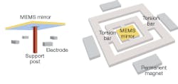
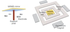
These three characteristics are interdependent, with the resonant frequency being inversely proportional to the mirror’s radius and the square root of its maximum tilt angle, which can create a quandary for some applications. One attempt to solve this dilemma was to use a digital mirror device (DMD) that utilized many small mirrors with a high switch frequency to form a single large mirror (for example, 1024 x 768 binary MEMS mirrors for a total array size of 14.0 x 10.5 mm). There are drawbacks to this approach, however, such as loss of power in the mirror gaps and edges, and pixel-to-pixel discontinuity, which would be expected to cause unwanted diffraction effects leading to a higher divergence angle and degraded beam quality. Even worse, as the tilt angle of the array mirrors increase, the size of the gaps and the corresponding problems also increase. But probably their greatest weakness is that they typically use the support-post design (see Fig. 1), which works well for projection television but does not tolerate more rugged conditions such as in military vehicles.
Torsion-bar MEMS designs in the past had maximum tilt angles of ±12° and diameters of 1.5 mm, but current versions not only have a more rugged design but can operate at 5 V rather than the typical 100 V or more. Not only are these designs able to tolerate high impact and vibration but their maximum tilt angles are now in excess of ±30° and they have diameters larger than 6 mm. Moreover, as mentioned earlier, their tilt angle range can be optically extended.
Flash ladar
Much research has been done to develop a single-pulse ladar called “flash ladar” using a focal-plane array (FPA)-a 2-D array of photodiodes that has no moving parts and is therefore more rugged. Though it has significantly worse range resolution than scanning ladar and, in addition, has some other manufacturing and image-processing issues, the greatest hurdle of flash ladar is unfortunately a fundamental problem that makes it impractical for most uses.2
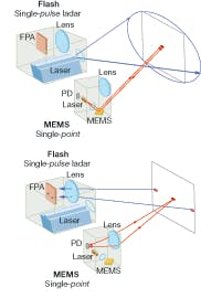
Flash ladar’s problem derives from its mode of operation (single-pulse), for which the number of photons reflected from the target is much smaller than that for a MEMS (single-point) ladar because it must illuminate the entire target area rather than just 1/(256 x 256) of the target area (see Fig. 2, top). Therefore, a flash-ladar system in this example requires a laser at least 65,000 times more powerful than that used for MEMS ladar to yield the same number of incident photons per pixel for the surface area of the target. Furthermore, the reflected pulse energy from the laser must be distributed over the entire FPA, resulting in another decrease in the number of photons per detector (see Fig. 2, bottom); assuming that both systems have similar performance characteristics, this means that for a 256 x 256 image the flash ladar would require a laser at least 4 x 10⁹ times more powerful than the MEMS ladar to yield the same return-signal strength per pixel.
Flash ladar does have a resolution advantage over MEMS ladar when the field of view is narrower than what single-point ladar is able to resolve (for example, less than 5° FOV). The laser-power problem remains, though, and while increasing the duration of the pulse increases the number of photons per detector, it also causes a significant loss in range resolution. Although using multiple pulses theoretically could help, it would be difficult to do with high-resolution real-time imaging because the use of an FPA is processing-intensive. Another alternative would be to use continuous-wave ladar methodologies that would require less laser power, but such techniques would also worsen range resolution by several orders of magnitude.
Hybrids and applications
A synergistic combination of flash and MEMS technologies has been designed that extracts the advantages of each. The time-of-flight issues that limit the resolution of single-point ladar and the laser-power problem of single-pulse ladar can be overcome through the integration of MEMS ladar with a small FPA. By just adding a 16 x 16 FPA detector to a 256 x 256 scanning MEMS ladar, a 16-megapixel image can be achieved in real time. For an equivalent flash ladar to achieve the same resolution, it would need more than 1012 times more laser power than the hybrid to have an equivalent number of photons per detector. These ladar hybrids could be integrated with a CCD to create high-resolution 3-D digital imaging for movie, television, video, and still cameras.
Considering that current ladar devices are about the size and weight of bowling balls, it may be hard to believe that a device based on current 2‑D torsion-bar MEMS scanners could have the footprint of a business card. These miniature ladar units could be integrated into a soldier’s helmet or an unmanned aerial vehicle with GPS (global-positioning-system) capability and a transmitter for real-time creation of a virtual 3-D battlefield.3 Similar units could be aerially dropped en masse for real-time border surveillance or the imaging of hostile territory because they can be mass-manufactured at relatively low cost. In addition, many diverse commercial applications other than 3-D cameras are anticipated that would initially involve the automotive, robotic, engineering, medical, forensic, scientific, and gaming markets.
Although this next generation of miniature real-time 3-D ladar will need to initially develop new markets and applications, it will eventually take over current ladar, similar to what cell phones did to pay telephones and are now doing to many land lines. The comparison of ladar to such disruptive technologies as cell phones and GPS is appropriate in that they were all initially rather large and expensive, and no one could envision their ultimate markets and volumes. Miniature ladar such as MEMS, flash, and their hybrids are but the next step in that evolution.
REFERENCES
1. W. C. Stone et al., NISTIR 7117 (May 2004).
2. B. Miles and J. C. Dries, AFRL Briefs (April 2004).
3. J. P. Siepmann and A. Rybaltowski, Military Communications Conference 2005 (MILCOM 2005) 1 (October 2005).
JAMES P. SIEPMANN is a founder of LightTime, 3555 Moser Street, Oshkosh, WI 54901; e-mail: [email protected]; www.LightTime.com.
Ladar adds dimension
Ladar (laser radar) is the visible-light analogue to radar, in which electromagnetic radiation is used to produce a set of 2-D or 3-D measurements that describe a target object. A 3-D ladar arrangement combines lateral with range (depth) information; the result is a set of coordinates and intensities that allows 3-D images of the target to be constructed. Typically, range is found by time-of-flight measurements of one or more laser pulses, while lateral information is gathered by a 2-D imaging detector (either scanned or staring). Along with its many military applications, ladar can be used in forensics, for scanning structures such as buildings, bridges, hazardous-materials containers, or as a sensor that serves as a robot’s “eyes.”
John Wallace


