SAMUEL SADOULET
Markets such as biomedical instrumentation and semiconductor processing are fueling the use of the ultraviolet spectrum. The nature of UV applications has changed dramatically over the past decade, primarily due to the availability of higher-power light sources at shorter wavelengths. The result is a new wave of product development in UV reflective optics that relies on the latest design, analytical, and production techniques to optimize performance.
One of the most active areas of new product development involves multispectral narrowband and broadband (UV through IR) applications such as fluorescence and spectroscopy. Designs for these applications can be either refractive (lens-based) or reflective (mirror-based), but it is the reflective systems that are drawing the most interest. Reflective systems are fully chromatically corrected by nature, making them a cost-effective way to get extremely broadband transmission. Their main drawback is that they can correct for only small angular fields.
The most common compound reflective systems used within these types of applications are reflective objectives. These objectives are typically relatively simple designs, comprising two to three reflective elements optimized for position, radius of curvature, and asphericity, and are commonly available in magnification ranges from 10x to 75x. Specifics of the coatings, field of view, and obscuration are highly dependent on the manufacturer. The optics can be designed to be finite conjugate for most imaging or infinite conjugate for focusing of laser beams.
The alignment sensitivity of the elements within the assembly, along with other subtle effects that arise from the shortness of the UV wavelengths, force the designer to be extremely diligent in the analysis of such systems to avoid problems during production. A variety of sequential tolerance-analysis algorithms are available, all slightly different. What they have in common, however, is that they all rely on perturbing the nominal system to model the effects of production tolerances. Perturbing the system allows the designer to understand its driving sensitivities and minimize the resulting degradation in performance, either by modifying the design or developing suitable production techniques. This type of tolerance analysis for reflective systems is identical to that used in refractive systems and is a well-known technique.
Additional analysis required
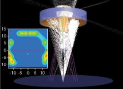
Sequential tolerance analysis may not be enough for UV reflective systems, however. There may also be a need for stray-light analysis (see Fig. 1). This approach allows modeling of the unintended energy that reaches the detector or exposure surface. This unintended energy is typically the cumulative contribution of ghost reflections, diffractive effects, and scattering surfaces in the system, and can be thought of as noise from the optical system. Stray light reduces the signal-to-noise ratio (S/N) of the system, which can be detrimental in the low-noise scenarios typically required in UV applications.
Ultraviolet reflective systems can be quite susceptible to stray light. They must often handle both low- and high-angle ray paths, which can be challenging to manage. For instance, in laser-focusing or fluorescence applications there is a great deal of low-angle (laser) and high-angle (fluorescing or focusing beam) energy within the system, producing a significant amount of stray light. An additional factor is that every optical surface in a reflective system tends to be coated for maximum reflection within the spectrum of interest. Refractive systems, in contrast, can control secondary reflection by using antireflection-coated optics. Coating the optics to maximize reflection essentially amplifies the need to control stray light extremely effectively. This control typically includes baffling and appropriate optomechanical geometry. For instance, strategically placed apertures and the treating or threading of problematic surfaces can be useful approaches to trapping or redirecting the stray-light energy.
Reflective systems are usually obscured, meaning that a certain portion of the light is blocked by a second or third element. In addition, some systems use off-axis geometries to maximize the nonobscured portion of the acceptance angles, thus improving the overall transmission of these systems. Both obscuration and off-axis geometries can be accurately and quickly analyzed with nonsequential ray-tracing programs.
Optomechanical design
In addition to examining the optics, designers need to consider the housing’s optomechanical design. The housing greatly influences optical performance, not only because it holds the optics in place but because it is often used to create a sharp obscuration or other critical baffling features. The mechanical parts that form the baffles are by no means perfect; they are not smooth, they are not sharp, and they are not particularly absorptive. Ultraviolet systems are particularly sensitive to these effects because these defects can be more significant at shorter wavelengths. Designers thus should use scattering models of the housing when developing high-S/N optics.
Time spent in the analysis of a design has proved essential to bringing that design successfully into production. Experience has shown that more than three-quarters of the time spent on developing reflective UV optical systems must be dedicated to analysis-both tolerance and stray-light-to ensure a smooth implementation in production.
Advanced production techniques
While system analysis can help predict problem areas within a design, developers eventually reach a point of diminishing return when working to desensitize the design. At that point, a designer needs to take advantage of advanced production techniques to satisfy system performance requirements. These techniques are available at mirror-fabrication and system-assembly levels.
In general, UV systems are more susceptible to tolerance errors than their visible counterparts, but of particular concern is surface accuracy. Surface accuracy is a measure of the deviation the final manufactured surface has from its nominal design curve. Accuracy is typically expressed in waves or microns, but wave specifications can be misleading in UV applications. Specifying a surface accuracy of 1/4 wave typically refers to the 632.8 nm wavelength of the HeNe line. For visible applications, surfaces accurate to 1/4 wave might be acceptable; in the UV region, however, this irregularity appears grosser because of the shorter wavelengths. A 1/4-wave surface measured at 632.8 nm is equivalent to 0.8 waves at 193 nm. As the wavefront quality becomes increasingly critical in UV applications, production will need to achieve 1/20 wave at 632.8 nm.
This surface accuracy can be produced using traditional polishing techniques; however, these techniques can be quite time-consuming. Recent developments in deterministic polishing techniques, such as MRF (magnetorheological finishing), provide an excellent alternative for the rapid production of high-accuracy surfaces. These deterministic polishing methods are based on measuring the surface using an interferometer and then selectively polishing certain subaperture areas, usually 3 to 8 mm spots (equivalent to 1/5 to 1/20 of the total clear aperture), to correct the final surface. These methods ensure the fabrication of a high-quality surface-1/20 wave is quite typical-straight from the polishing machine.
These new production techniques also offer designers a promising design option. Given the requirement for higher numerical apertures or greater light throughput on UV optical systems, it is evident that huge gains can be achieved by integrating aspheric surfaces rather than the traditional spherical ones. The trick to designing with aspheres is to make them easily producible in a cost-effective scenario. This means keeping the number of aspheric constants to a reasonable number; an eighth-order upper limit on an even asphere is usually more than adequate. New metrology and CNC (computer numerically controlled) polishing machines have enabled the production of fast aspheres, and wider use of aspheres within optical solutions is bound to fuel major product developments in UV optics in the coming years.
A reflective element’s manufactured surface is important, but designers also need to look at coating design. Factors to consider include spectral band, reflection/absorption/transmission characteristics, power-damage threshold, environmental conditions, and coating lifetime. A variety of companies offer proprietary coatings for application to UV optics that can ensure optimal performance within specific applications.
Assembly with feedback improves alignment
In addition to these fabrication practices, designers must consider system assembly. The first issue to attack is to make sure that the optical elements are in stress-free mounts so that the optical surfaces are not distorted from their original shapes. Although avoiding distortion is relatively easily accomplished with visible-light optics, the stringent surface-accuracy requirements at the shorter UV wavelengths make optical mounting an interesting problem for UV systems. The trick is primarily in understanding the fundamentals of mechanical stress and researching specific optomechanical adhesives that would be compliant enough to allow the assembly to move under thermal cycling without stressing the optic. Many of the current strategies designers can use are borrowed from established astronomical optomechanical techniques, such as finite point-contact mounting, shimming and cementing approaches, and optimization of material matches for thermal and stress management.
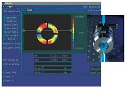
After assembly comes alignment, an additional challenge for reflective systems. Reflective systems are often designed for maximum light collection (or delivery). This is one of the underlying reasons why reflective-system performance is typically very sensitive to the placement of the mirrors, particularly in terms of misalignment of the centerline and tilts of the elements with respect to each other. Addressing this sensitivity requires techniques that actively align elements under interferometric (or similar) observation to optimize the system performance during the assembly process. Many proprietary techniques (based on, for example, interferometric and star-test-based instruments) accomplish this effectively; all of them rely on accurately placing elements based on a feedback mechanism measuring system performance.Devising a method to ensure that the assembly does not go out of alignment during deployment is difficult. As a consequence, most reflective-objective designs need to be periodically realigned using targets and access setscrews. In contrast, the ReflX, a reflective objective produced by Edmund Optics, is designed to perform through shock and vibration; it does not have to be realigned in the field (see Fig. 2). This property was achieved through manufacturing approaches that include using durable locking mechanisms of exotic materials, as well as optimizing the dissipation of mechanical loads through finite-element analysis.
Optical manufacturers rely on such state-of-the-art engineering tools and production techniques to design and adequately yield high-performance UV optics in volume production. Developments within the UV spectrum are resulting in a new generation of optical systems that can deliver unprecedented cost-effective performance for laser-line and broadband applications. This demand will result in a new wave of products that will match or exceed these requirements.
SAMUEL SADOULET is director of product development at Edmund Optics, 101 E. Gloucester Pike, Barrington, NJ 08007; e-mail: [email protected]; www.edmundoptics.com.
