![FIGURE 1. Conceptual mapping from a point source to a freeform surface (P) to a set of target points (yn). The surface normals (Pn) are set to send the incident rays to their corresponding target points. The surface is then created using a B-spline surface interpolation [2]. FIGURE 1. Conceptual mapping from a point source to a freeform surface (P) to a set of target points (yn). The surface normals (Pn) are set to send the incident rays to their corresponding target points. The surface is then created using a B-spline surface interpolation [2].](https://img.laserfocusworld.com/files/base/ebm/lfw/image/2016/02/1601lfw_jac_f1.png?auto=format%2Ccompress&w=250&width=250)
JAKE JACOBSEN and WILLIAM CASSARLY
The use of freeform optical elements in illumination applications has received a great deal of attention in recent years. For applications with specific target requirements and relatively compact sources, freeform optics offer the ability to precisely tailor the resulting illumination pattern to meet system requirements, enhance the visual appeal, and improve energy efficiency.
Calculation techniques and the resulting design software have been available for years.1 However, it was only recently that the capability to design freeform surfaces was effectively integrated into a fully capable illumination-design software package. Because of this integration, the design and use of reflective and refractive freeform optical elements has become a practical endeavor for a wide range of illumination applications and designers. The inclusion of a freeform design capability in an illumination-design software package allows the designer to integrate freeform elements with other optical components to build more complex systems, add real sources, and use automated tools to analyze the resulting illumination pattern.
As part of its LightTools illumination design software, Synopsys recently introduced the Freeform Designer as an integrated capability in the software's Advanced Design Module. The Freeform Designer can be used to calculate freeform reflective and refractive surfaces based on an illuminance or intensity target distribution, source collection angle and distribution, and several other geometrical settings. The following examples highlight some practical considerations when designing freeform illumination optics.
Target mapping
The calculation of the shape of a freeform surface is based on a mapping of a known source angular distribution to a desired target distribution. That target distribution can be angular or spatial, depending on the need. If we know the distribution of light on the freeform surface as a function of position on the surface and incoming angle, then we can tailor that surface so that the outgoing light meets the desired target distribution either on a specified surface, or in angle space (see Fig. 1).
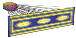
While this is conceptually simple, implementing it in the general case—where symmetries cannot be assumed—can be complex. Nevertheless, the problem is tractable, and surfaces can be computed for both simple and complex targets (see Fig. 2).Inherent in the approach is a one-to-one mapping. Rays incident on a given point of the freeform surface are assumed to have the same angle of incidence. This implies a point source or, alternatively, a collimated source. Rays emitted by an extended source will strike a given point on the freeform surface at different angles and thus will strike the target at slightly different locations (or slightly different angles for intensity targets), causing a blur in the target pattern. The extent of this effect is dependent on the angular size of the source as seen from the freeform surface. Because of this, smaller sources such as LEDs and discharge sources tend to produce less blur.
Since the angular size of the source as seen from the freeform surface directly affects the extent of the blur, a good method for reducing the blur size is simply to place the freeform surface farther away from the source. This reduces the apparent source angular extent, which reduces the target blur. Of course, the tradeoff is that the optic will increase in size.
Surface sampling
The mapping method described above is, by its nature, discrete rather than continuous. The surface and target must be broken down into sections so that the resulting surface point grid can be fit with a B-spline surface. The number of points used to describe the freeform surface can have an impact on the fidelity with which the target can be reproduced. We have found that targets without small-scale contrast variations can usually be represented with about 25 × 25 points across the surface. Examples of such targets are uniform and Gaussian distributions (see Fig. 3). In contrast to this, targets with significant high-contrast structure can require a significantly larger number of surface points. Figure 2 shows such a target-for its surface, we used an 85 × 51 grid of points.While increasing the number of grid points on the surface does increase target resolution, it can substantially increase the amount of time needed to calculate the freeform surface—from much less than a minute in many simple cases to many minutes for complex cases. The times cited here are for a midrange laptop where the calculation algorithm uses a single CPU.
Collection efficiency
With nearly all illumination systems, one goal is to maximize the throughput of the system. Since most sources emit into a wide distribution, this usually means increasing the size of the freeform surface to increase the collection angle and gather more light. This is an effective approach, but it can have drawbacks.
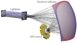
For a reflective system, increasing the collection angle often causes the returning light to be blocked by the source itself and its support structure. While this may be tolerable with segmented reflectors, the one-to-one mapping used with freeforms will lead to hard shadows in the target pattern. To avoid this, reflective systems are usually designed to be off-axis, sending the returning light past the source on one side. This technique alone may not be sufficient for situations with wide target distributions, where the returning light bundle is diverging, or for wide collection angles, where the returning beam bundle is simply too large. In these cases, the reflector can be configured to cross the rays so that the rays on one side of the reflector are sent to the opposite side of the target. This creates an intermediate focus region. While this usually creates a deeper reflective optic, it also creates more clearance for the source (see Fig. 4).For refractive surfaces, the collection issue is somewhat different. As with reflective elements, increasing the collection angle increases the size of the optic, but also increases the collected energy. The limitations come when the incident angles at the edge of the optic approach the critical angle. At this point, increasing the collection angle further will cause rays at the edge of the optic to undergo total internal reflection. Even for rays approaching the critical angle but still refracting, the Fresnel losses become significant and require active compensation.
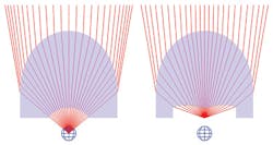
To avoid these problems, but still collect as much light as possible, we can use both the first and second surfaces of the lens. One approach to accomplish this uses a Cartesian oval profile for the first surface and tailors the second surface. Cartesian oval refractive surfaces can perfectly focus light from one point to another point or, in this case, from a point to a virtual focus. With this technique, what we can do is move the source forward from its initial position to a point closer to the freeform surface. We then construct a Cartesian oval surface that causes rays from the new source location to bend, creating a virtual focus at the original source location. In this way, the refracted rays that are then incident on the freeform surface appear to have the same collection angle as before, emanating from the original source location, while the actual collection angle is much higher. To put it another way, we collect more light by making the Cartesian oval surface do some of the work (see Fig. 5).The integration of a capability that quickly and easily calculates freeform surfaces in the LightTools design software environment will allow for greater use of freeform optics in illumination by facilitating their design and analysis.
REFERENCES
1. R. Wester and A. Bäuerle, Adv. Opt. Technol., 2, 4, 301–311 (2013).
2. L. Piegl and W. Tiller, The NURBS Book, Springer Science & Business Media, Berlin, Germany (2012).
Jake Jacobsen is technical marketing manager and William Cassarly is a scientist at Synopsys, Mountain View, CA; e-mail: [email protected]; https://optics.synopsys.com.


