Magnetorheological finishing automates precision optics fabrication
Don Golini
With surface figure requirements of 0.005 l rms common in photolithographic optics, component specifications often exceed the capabilities of commercial high-speed optical-fabrication equipment. Even after front-end processing with computer numerically controlled (CNC) grinding and polishing equipment and final figuring with advanced technologies such as ion-beam figuring and computer-controlled polishers, optical elements still require significant work by master craftsmen, leading to problems with reliability, predictability, throughput, cost, and skilled-work-force availability.
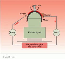
Deterministic polishing equipment based on magnetorheological finishing (MRF) automates the final-figuring step, which becomes more critical as production de mands increase (see Fig. 1). Our Q22 production MRF system, scheduled for installation at Silicon Valley Group Lithography (Wilton, CT) and Tropel Corp. (Fairport, NY), will be used to polish optical components for semiconductor photolithography applications.
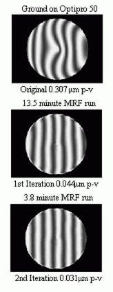
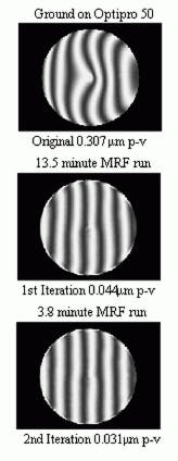
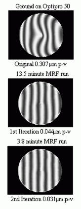
Based on the MRF process invented in Belarus and fine-tuned at the Center for Optics Manufacturing at the University of Rochester (Rochester, NY), the Q22 computer-controlled multiaxis machine simultaneously eliminates subsurface damage and improves figure. Material-removal rates are high and cycle times are short, so it takes only minutes to produce figure accuracy better than l/20 peak- to-valley (p-v) (see Fig. 2). The process works well on flats, spheres, and as pheres, but its ability to produce high-precision optics is its greatest contribution (see Fig. 3).
The MRF process uses magnetorheological (MR) fluid as a compliant replacement for a conventional rigid lap, so the polishing tool never dulls or changes as it adapts to complex shapes. The MRF system magnetically manipulates the viscosity of the fluid where it touches the workpiece surface to create a subaperture polishing lap conforming to the surface.
A closed-loop circulation system maintains MR fluid for reuse, using a fluid-delivery system to mix about a liter of fluid vigorously, while continuously monitoring and controlling its properties such as temperature and viscosity. Once drawn out of the mixer with a peristaltic pump, the fluid passes through a pulse dampener and is extruded onto a spherical wheel rotating at about 1 m/s. The thin ribbon of fluid carried over the top of the wheel enters a suction cup and is fed back into the mixer.
An electromagnet located directly under the polishing wheel uses specially designed pole pieces to induce a strong local magnetic-field gradient across the top section of the wheel. Magnetorheological fluid passing through the field solidifies in milliseconds, then returns to its original state on exiting, again in milliseconds. The zone of magnetically stiffened fluid at the wheel apex becomes the polishing tool when an optical surface is placed in it such that the ribbon of fluid is squeezed from about 2 mm in thickness to 1 mm. The fluid produces significant shear stress and polishing pressure, while automatically conforming to the local curvature of the part being polished.
The MRF process requires two input functions. One describes the process removal rate and distribution (the polishing tool), the other describes the initial surface error. A PC-driven software algorithm performs a deconvolution of the two functions to predict how well the polishing tool can fix the error and then feeds related instructions to a four-axis CNC machine. The machine positions the lens through the fluid to maintain a constant gap and surface normal for arbitrary shapes, including plano, spherical, or aspheric surfaces. Deterministic removal occurs by varying the dwell time as a function of the rotating lens` position in the fluid.
Asymmetric figuring
For MRF to work in high-precision (better than 1 l p-v) applications, it must eliminate even the lowest-amplitude asymmetries produced by prior manufacturing steps, regardless of preparation techniques. One advantage of the MRF process is the user`s capability to control variables such as fluid viscosity, magnetic-field intensity, lens sweep rate through the fluid, and fluid velocity. Another advantage is a recently developed control strategy to correct nonrotationally symmetric errors such as astigmatism.
During polishing, preferential dwell time produces preferential material removal. The longer any lens area is immersed in the fluid, the more material the process removes. The system varies dwell time by varying the sweep rate of the lens through the MR fluid. As dwell time in the axial plane is varied, good precision on rotationally symmetric features is achieved. For asymmetric errors such as astigmatism, the Q22 varies the spindle-rotation rate to effectively dwell longer on high zones than on low zones. If an optical surface has a saddle shape, in one revolution, the lens spindle will rotate faster over the two low parts of the saddle to reduce dwell time and slower over two high parts to increase it. Over many revolutions, there is preferential polishing of the highs in the saddle over the lows, with simultaneous correction of rotationally symmetric errors (see Fig. 4).
The MRF equipment also shows promise in optics applications ranging from ophthalmic-lens manufacture and semiconductor-wafer polishing and planarization to finishing of advanced ceramic components. Specific possibilities include the small spherical and aspheric optical elements for the National Ignition Facility (Lawrence Livermore National Laboratory), commercial and military imaging systems in the visible and infrared, and prototypes and tooling for high-volume commercial applications. o
FIGURE 1. In magnetorheological finishing, magnetically manipulating viscosity of the fluid contacting the workpiece creates a subaperture polishing lap conforming to the optical surface. The interferometrically characterized polishing tool never dulls or changes.
FIGURE 2. A ground optical surface at 0.307 µm p-v (top) is MRF-polished in 13.5 min to 0.044 µm p-v to eliminate subsurface damage and improve figure (middle). A second polishing run of 3.8 min improves figure to 0.031 µm p-v (bottom).
FIGURE 3. A six-minute, two-iteration MRF run, with symmetric and asymmetric figuring, polished a 38-mm-diameter fused silica window at l/3 p-v /l/14 rms (left) over 90% of its aperture to l /30 p-v/l/250 rms (right).
FIGURE 4. A single-iteration asymmetric figuring run with MRF took this 5-in.-diameter fused-silica window from l/5 p-v / l/22 rms (top) to l/16 p-v / l/100 rms (bottom).


