Fused couplers increase system design options
Enhancements to all-fiber devices, such as fused biconically tapered fiber couplers, will play an important role in the DWDM environment.
Francois Gonthier
Passive components can be divided into three main categories based on the technologies used to produce them: integrated optics, micro-optics, and all-fiber devices. Integrated-optical devices, which multiplex a large number of wavelengths on a single optical chip, and micro-optical devices, in particular those using thin-film filters, are currently the most commonly used. But all-fiber devices also have an important role to play, especially because of the unequaled wavelength selectivity of fiber Bragg-grating filters. Enhancements to other all-fiber devices, such as fused biconically tapered (FBT) fiber couplers, have produced interesting new multiplexing devices that represent an important addition to the list of reliable dense-wavelength-division-multiplexing (DWDM) components available to the communications design engineer.
In wavelength-division-multiplexing (WDM) systems, a number of optical wavelengths are transmitted on a single fiber, thus carrying several signals simultaneously and independently. In contrast to electronic-based multiplexing schemes, each WDM channel is independent of the others in bit rate, protocol, and direction. Two-channel WDM systems based on 1310 and 1550 nm have been common until recently. But improvements in laser-diode stability and wavelength accuracy, as well as the emergence of the erbium-doped fiber amplifier (EDFA)--which provides broadband channel-independent amplification--now allow many closely spaced channels to share a fiber.
Dense WDM systems offer designers increased capacity by providing two to 32 channels. Increased flexibility arises because of channel independence: each channel can be routed--passively and optically--to a particular destination, offering tremendous potential for future expansion and evolution. This puts DWDM components at the forefront of system design, because their characteristics ultimately define how many wavelengths can be used and how their use can be distributed throughout a network.
Fused-fiber components cannot replace every other type of component available today, but they offer a high-performance alternative for particular applications, especially those in which low insertion loss, high directivity, or great flexibility is needed. In addition, because they are all-fiber devices, their integration into fiberoptic networks is generally straightforward, and their use is cost-effective.
Fused cladding
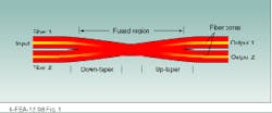
In its simplest form, an FBT fiber coupler consists of two optical fibers in which the optical cladding has been fused together (see Fig. 1). The structure is tapered by elongation, while it is hot, until appropriate coupling properties are achieved. It is then bonded to a substrate and encapsulated into a compact and rugged package.
The first fused couplers, which used multimode fiber and provided only simple power distribution between fibers, were produced in 1977 by B. S. Kawasaki and colleagues.1 The same group extended the technique to single-mode fibers in 1981. An analysis by J. Bures and others in 1983 provided insight into the inner workings of the device and opened the door to new applications, including WDM.2 Since then, fused couplers have grown from their simple original structure to more precise and complex structures suitable for advanced applications such as DWDM.3-6
The basic principle of operation of all fused-fiber couplers is the same--the fusion of two or more fibers into a new waveguide structure in which several fiber cores share a common optical cladding. Tapering this structure changes the core modes of the fibers, broadening the modal fields in the cladding. In the "down" taper direction, modes can escape the cores to become common cladding modes that overlap all the fiber cores present. In the "up" taper region, the cladding modes are converted back into fiber-core modes. Which particular cores recover power depends on the relative phase between the cladding modes.
The conversion between the core and cladding modes is virtually lossless if the taper slopes are gradual, making FBT components the lowest excess-loss passive devices available. Furthermore, signal light never leaves the optical-fiber structure and thus never encounters an interface or discontinuity, so there is intrinsically no possibility of backreflection. These components, therefore, display very high directivity.
Classical interferometer
In a 2 ¥ 2 single-mode fused coupler, only two modes are involved in the coupling process. Because of the transverse symmetry, interference between these modes can produce a complete transfer of power between the two fiber cores. This two-mode coupler is analogous to a classical interferometer that has two optical paths, such as a Mach-Zehnder unit. The single-mode fused coupler has a sinusoidal output as a function of the phase between the modes, with the two output ports having complementary transmissions. The phase difference between the modes depends on the transverse and longitudinal profiles of the fusion region, but is approximately linear with wavelength. If the wavelength period of the coupler is very large, the coupler can be used as a fixed splitter with any desired coupling ratio. If the period is small, it makes a good wavelength multiplexer. When the period is very small, it becomes a useful DWDM component.
As in any two-path interferometer, the optical path difference must be large to yield high spectral sensitivity. Because a fiber coupler is a birefringent structure, however, longer length leads to greater polarization dependence. This drawback is the main reason fused couplers have not been widely used in DWDM systems, although they have been common in conventional WDM systems for some time. To create a satisfactory dense wavelength-division multiplexer or demultiplexer, the two polarization states must be closely matched to maintain good isolation. This can be accomplished by careful control of the fabrication process.
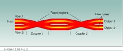
A second way to achieve dense wavelength response is with an all-fiber Mach-Zehnder structure, using two fused couplers with 50/50 coupling ratios in series on two optical fibers (see Fig. 2). This four-port device behaves much like a coupler. But the optical path difference between the two arms results in a sinusoidal wavelength response with a very small polarization dependence, because the couplers themselves are very short. Multiple-wavelength multiplexers and demultiplexers can be built using either of these two designs.
Multiplexers and demultiplexers
To achieve multiplexing or demultiplexing, only three of the four couplers or Mach-Zehnder device ports are used. The devices are symmetrical and can be used as multiplexers (two input ports to one output port) or demultiplexers (one input to two outputs).
To demultiplex two wavelengths, the transmission maximum of one port is set to one of the wavelengths, and the wavelength period of the device is set to twice the channel separation--so the transmission in the second output fiber is maximum at the second wavelength. The period of a coupler, determined by its length, can be adjusted from large (that is, 1310/1550 nm) to very small (0.4 nm, which corresponds to 50-GHz spacing). The Mach-Zehnder structure can be used to produce even smaller channel spacing--stable 0.4-nm structures have already been made. The maximum and minimum positions are fixed solely by the fabrication process and great flexibility exists in the selection of wavelength and spacing.
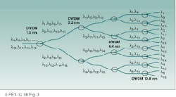
A single coupler will multiplex two wavelengths, and several must be combined for greater numbers. For N wavelengths, N-1 couplers are required, arranged in a tree structure (see Fig. 3). For example, a 16-channel demultiplexer for a system with 1.6-nm spacing has a first stage composed of a single coupler that demultiplexes to two combs of eight wavelengths each, spaced at
3.2 nm. A second stage of two couplers, in series with the first, demultiplexes the two combs into four combs of four wavelengths each, at a 6.4-nm channel spacing. A third stage of four couplers splits these into eight pairs and, finally, a fourth stage of eight couplers separates the pairs into 16 distinct channels. At each stage, the wavelength spacing between channels in a given fiber is twice that in the previous stage. This increase in channel spacing makes high isolation easy to achieve.
The insertion loss of such a composite device is small (less than 2 dB) because the loss of the individual couplers is small and because each wavelength passes through only one coupler per stage. Although 15 couplers are used in the example given, each individual wavelength traverses only four. And because all channels pass through the same number of components, channel uniformity is very high.
The sine response of a coupler can be an advantage in some instances and a limitation in others. The excess loss of fused couplers is very low (less than
0.2 dB, even for very dense multiplexers), so if the passband tolerance is less than 20% of the channel spacing, the insertion loss will be very close to the excess loss. In applications such as multiplexing 980-nm pump lasers to achieve greater power in EDFAs, coupler performance can be optimized with the laser source to reduce the channel insertion loss to 0.5 dB for four-channel multiplexers.
Channel isolation
For larger passbands, the insertion loss increases slightly (0.9 dB for a passband of 50% of channel spacing). In multiwavelength multiplexers, the increase primarily affects the insertion loss of the first-stage coupler, because the channels are more widely spaced in the later stages. A more significant consequence of this larger passband is the limitation it places on channel isolation: peak isolations of greater than 25 dB are reduced to 10 dB or less in the passband. Wavelength filters must be added to achieve high isolation.
Although satisfactory thin-film filters exist, all-fiber types can achieve very high isolation with lower insertion loss in the passbands. The best-known devices are Bragg gratings, which feature very narrow, sharp responses and high reflectivity, with very low insertion loss at other wavelengths. The use of such gratings can easily add 30 dB of isolation, but, because they reflect power, they can be used only following the demultiplexing couplers. Because the undesired, reflected channel goes through the couplers twice, doubling the isolation they provide, return power can be held to a reasonable level.
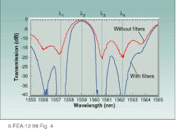
Gratings are very effective for narrow channel spacing (1.6 nm or smaller), but are less attractive if the band to be isolated is greater than 5 nm, a requirement better met by tapered-fiber filters. These are made by tapering a single fiber so as to produce coupling between cladding modes. Their response resembles that of a branch of a coupler, with unwanted modes lost in forward-propagating cladding modes instead of being transferred to another fiber. These filters display a sinusoidal response that is independent of polarization--unlike the case with couplers--because the filter maintains the circular symmetry of the fiber. A filtered demultiplexer can provide more than 40-dB isolation between channels (see Fig. 4).
Other technologies
In micro-optical devices, light exits the fiber and is guided through lenses, mirrors, and filters that collimate and separate light beams to achieve the desired optical effect. Two approaches are used to divide wavelengths--interference thin-film filters and surface gratings. Interference filters are known for step-like cut-off characteristics or door-like bandpass functions. Devices using surface gratings have responses that are more Gaussian.
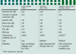
An integrated-optical device consists essentially of optical waveguide circuitry fabricated on a substrate, connected to input and output fibers. Wavelength selectivity is achieved either with surface or Bragg gratings, or with Mach-Zehnder interferometers or arrayed waveguides (see table). As with fiber couplers, these devices have a sinusoidal response, except for arrayed waveguides, whose response is approximately Gaussian. o
REFERENCES
1. B. S. Kawasaki, K. O. Hill, and R. G. Lamont, Opt. Lett. 6, 327 (1981).
2. J. Bures, S. Lacroix, and J. Lapierre, Appl. Opt. 22(12), 1918 (1983).
3. S. Lacroix, F. Gonthier, J. Appl. Opt. 33(36), 8361 (1994).
4. A. Symon, S. Lacroix, and J. Bures "Dense all-optical fiber WDM," Proc. SPIE Photonics West `96, San Jose, CA, 114 (1996).
5. F. Ouellette, Laser Focus World 34(3), 83 (March 1998).
6. F. Gonthier et al., Appl. Phys. Lett. 54(14), 1290 (1989).
FIGURE 1. Cladding of a pair of optical fibers is fused together to form a simple fused biconically tapered fiber coupler.
FIGURE 2. Two fused fiber couplers can be combined to form an all-fiber Mach-Zehnder structure.
FIGURE 3. Fiber couplers can be arranged in a tree structure to multiplex multiple wavelengths--N-1 couplers are required to multiplex N wavelengths.
FIGURE 4. Channel response of a four-wavelength demultiplexer with 1.6-nm channel spacing shows that, with the filters, 40-dB isolation is possible. Some residual power appears between channels, but not enough to affect the channels themselves.
FRANÇOIS GONTHIER is chief technology officer at ITF Optical Technologies, 45 Boul Montpellier, Ville St.-Laurent, QC, Canada H4N 2G3.
