Telescope mirrors successfully lose weight
Telescope mirrors successfully lose weight
Replicating mirrors with graphite-fiber-reinforced composites keeps them thin.
Peter Chen
A new generation of extremely lightweight Earth-, space-, or Moon-based telescopes may be possible with a composite-mirror technology developed cooperatively by NASA and private industry. The optical replication technique has produced 0.6-m-diameter thin-facesheet mirrors weighing less than one kg, 0.9-m core-reinforced mirrors weighing 4 kg, and a 1.5 ¥ 2.5-m reflector array approaching 23 kg. Glass mirrors of the same surface areas, with a traditional 6:1 diameter-to-thickness ratio, weigh 60, 200, and 2700 kg, respectively.1,2
The drive to reduce telescope mirror weight is directly linked to the fact that the weight of the optics determines the type and weight of the support structure, drive mechanism, and--ultimately--the overall payload. Composite replica mirrors are, by far, the lightest of the new technologies shown at NASA`s recent Next Generation Space Telescope Technology Challenge conference held in Oxnard, CA (see Fig. 1). Potential applications for the new technology include meter-class portable telescopes for lidar, remote sensing, surveillance, and amateur astronomy, as well as large mirror arrays for light collection, space solar concentrators, flight training simulators, magic shows, and high-energy physics. Also possible is a radically new approach to building the next generation of very large (10 m plus) telescopes on the ground and in space at tremendous savings in cost and fabrication time compared to traditional techniques.
Graphite-fiber-composite reflectors are already standard fare in radio antennas and space communication systems. Composite replica mirrors--built with both the familiar graphite epoxy materials and newer graphite-cyanate-ester-resin composites--differ in that they combine extreme light weight with superb surface smoothness, something that had eluded earlier developmental efforts by the major space agencies. Lightweight composite mirrors, for example, have been verified with surface microroughness as low as 0.7 nm rms--smoother than the primary mirror of the Hubble Space Telescope at 2.5 nm rms.
Thin, but fit
Traditional mirror fabrication--grinding a glass blank to shape and coating it with a reflective surface film--achieves lightweighting by including special low-weight materials, making the substrate thinner, and possibly cutting holes in the back. The process is limited by the minimum thickness required for grinding and the need to avoid support print-through. Even when beryllium--the lightest material--is used, the areal density (mass/unit area) is 15-25 kg/m2. Areal density of the 2.4-m Hubble Space Telescope primary mirror, which uses a glass facesheet and eggcrate construction, is about 180 kg/m2.
Optical replication achieves areal density as low as 2 kg/m2 at a 0.6-m diameter--the lowest among the current lightweight technologies. The density is, for example, one third to one tenth of the areal density of silicon-carbide, carbon-fiber/silicon-carbide, and thin glass-shell mirrors. The figure is far below the 15 kg/m2 target of the Next Generation Space Telescope currently under study or the 12 kg/m2 target that the project is trying to reach with beryllium.
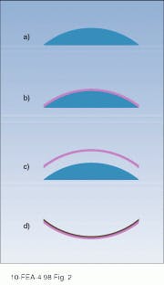
The first step in the optical replication process is to grind and polish a glass mandrel to the inverse of the desired shape (see Fig. 2). A convex mandrel is required for a concave mirror, and vice versa. Researchers then apply successive layers (or plies) of graphite-fiber-composite preimpregnated materials (prepregs) at different angles on the mandrel. The resulting laminate is then cured under heat and pressure, released from the mandrel, and vacuum-coated with a reflective coating such as aluminum magnesium fluoride (Al/MgF2) or silicon carbide (SiC2). The shell is only as thick as necessary to maintain figure, and core backings can be added to enhance stiffness.
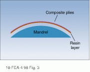
This sequence is almost the same as the conventional method for making composite laminates, with one major difference. Traditional lay-up techniques cannot produce smooth optical surfaces because the graphite fibers needed for stiffness and strength impart a rough texture to the surface that scatters light and causes errors in the optical figure. Composite Mirrors Applications (Tucson, AZ), codeveloper of the new fabrication technique, devised a successful strategy to overcome print-through of the graphite fibers. During the lay-up process, researchers introduce a very thin layer of pure resin between the prepreg material and the mandrel. The resin is cured along with the laminate and becomes the optical surface, eliminating surface fiber texture (see Fig. 3).
The thickness of the top resin layer is the critical parameter. If the layer is too thin, the fibers print through. If it is too thick, the resin assumes a bulk property and tends to debond or crack. Extensive trials found optimum resin thickness was found to be between 30 and 50 µm and indicated stability under vacuum and at cryogenic temperatures. Composite mirrors at the optimum resin thickness have been tested in vacuum and down to liquid nitrogen temperatures (77 K or -196°C) with no microcracking or delamination.
The flexible process can produce both thin-facesheet and honeycomb-core-reinforced mirrors, as well as fabricating both mirrors and support structures from the same composite material. In addition, ion-milling has no adverse effects on surface smoothness. There is active figure control, with as-manufactured figure accuracy as low as 1/5 wave rms (632.8 nm). Mid-frequency ripple is less than 1/30 wave rms (632.8 nm).
Composite replication also provides high product uniformity. As can be expected, replica mirrors made from the same mandrel show much less scatter than if each mirror were worked individually. This can lead to some very interesting applications such as extremely large telescopes with primary mirrors composed of hundreds of identical segments.
Equally important are the low fabrication costs. Optical replication works with standard composite cure ovens and vacuum coating chambers, and the graphite epoxy and graphite cyanate ester resins are widely available standard industrial products. In addition, fabrication requires only a small amount of the composite materials.
Production is rapid once a glass mandrel is on hand. For example, it takes about three weeks to lay-up and cure a 0.9-m mirror (specifications are single apertures to 0.9 m, coaligned mirror arrays to 1.5 ¥ 2.5 m ).
Toward perfect figures
An optic is diffraction-limited if its figure does not depart from a perfect surface by more than one quarter the
wavelength of light measured peak-to-valley--or roughly 1/19 wave rms. Composite mirror technology is quickly approaching this goal, but two problems must first be solved.
1. High tooling costs. At present, the major expense is the mandrel, which is more often than not required to be convex. As any optician will attest, it is more difficult to polish and test convex shapes than concave ones, so a convex glass piece typically costs ten times that of a concave glass piece of the same shape. Tooling costs are therefore high for fabricating large optics in units of one. On the other hand, many replicas can be made from a mandrel, allowing cost to be amortized over its useful lifetime.
2. Inherent figure errors. Precision mirrors made with composite laminates all have unavoidable figure errors, especially astigmatism. This comes about because the angles between plies can never be exact, and the fibers within individual plies have manufacturing tolerances that can limit how well they align. Computer modeling shows that this departure from perfect alignment of plies and fibers promotes a slight warping of the laminate which, while negligible by mechanical standards, is significant (several waves) in terms of departure from optical perfection.
Researchers report making almost daily progress on solving both problems. To address the tooling costs, they are commissioning the polishing of glass mandrels in the conventional fashion. Another option is double replication, which works from a concave optic of known figure and spin-casts epoxy to generate parabolas of arbitrary curvature and size.
To limit inherent figure errors, the approach is to fine-tune the replication process. This involves changing parameters such as prepreg material, ply thickness, fiber size, fiber density, resin content, lay-up schemes, cure temperature, cure time, and postcure cycling. Any residual figures errors are then corrected by active figure control. Required equipment will not necessarily be costly or complex. o
REFERENCES
1. P. C. Chen et al., Opt. Eng. 37(2), 666 (1998).
2. P. C. Chen and R. Romeo, "Fabrication And Testing Of Very Lightweight Composite Mirrors," Space Telescopes And Instruments V, Proc. SPIE 3356, P.-Y. Bely and J. B. Breckinridge, eds., paper # 3356-128 (1998).
FIGURE 1. A 24-in.-diameter mirror made of graphite composite wieghing about 0.75 kg is easily held by a child. A glass mirror of the same size and with the normal 6:1 aspect ratio would weigh about 52 kg.
FIGURE 2. Glass mandrel polished to the
complementary shape of the mirror desired (a) is coated with successive layers of graphite fiber composite preimpregnated material to form a laminate (b), which, when cured in an oven,
hardens into a shell and is released from the
mandrel (c); the shell is inverted and vacuum-coated with a reflective metal film (d).
FIGURE 3. To overcome print-through of the graphite fibers, a very thin layer of resin is introduced between the preimpregnated material and the mandrel; after curing, the resin layer becomes the optical surface.


