FLORIAN FOURNIER and WILLIAM CASSARLY
Freeform optics have become ubiquitous. You most likely have one in your pocket or purse right now on your cell-phone camera module. Freeform surfaces are used for most illumination tasks—from automotive headlights to streetlights—when applications with complex illumination requirements cannot be achieved with conventional, rotationally symmetric optics. Combined with light-emitting diodes (LEDs), illumination systems using freeform surfaces can yield compact systems with long lifetime, low power consumption, and high system efficiency. For instance, streetlights using these surfaces can achieve superior light control and therefore save energy while reducing light pollution. And freeform automotive headlight designs can increase performance while enabling innovative styles.
The freeform design challenge
Freeform surfaces are designed to convert light emitted by a source into a specified light distribution. However, streetlights, headlights, and antennas face the same design problem: finding a surface shape based on the radiation pattern it must produce. Despite decades of investigation, designing freeform surfaces has remained a challenging exercise, and frequently relies on tedious iterative processes and manual tweaking.
The steady increase in computational horsepower often gives the false impression that finding the appropriate freeform surface shape is a matter of applying a standard optimization algorithm. Designers commonly use spline surfaces with dozens or hundreds of variables, hoping that the optimization algorithm will determine the appropriate shape. Evaluating the extended source illumination pattern produced by a freeform shape with sufficient accuracy requires tracing hundreds of thousands—sometimes millions—of rays. Combined with dozens of optimization variables, the time required to explore such a large optimization space quickly becomes computationally prohibitive. Techniques to speed up ray tracing can help, but above all, the starting point and the choice of surface parameterization will make the difference. In order to design a freeform surface from scratch, it is often convenient to assume that the source is a point. There are two dominant surface construction methods available: the flux mapping method and the method of supporting ellipsoids.
Freeform design solutions
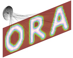
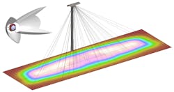
The flux mapping method consists of finding a correspondence (map) between the source and the desired target light distribution.1 The flux distributions of the point source and the target are both divided into bins containing equal amounts of energy. By comparing these source and target grids, each target location is associated with a corresponding source origination direction. The designer then simply needs to construct the surface that reflects (mirror) or refracts (lens) each ray direction to its corresponding target location. The simplicity of this method has some limitations. Mappings can only be easily established for simple light distributions. Additionally, there is no guarantee that the constructed surface will be smooth and continuous. While it may seem counterintuitive, some mappings cannot be achieved by a continuous surface! Unfortunately, surface discontinuities will often result in undesirable artifacts in the light distribution achieved by the manufactured surface (see Fig. 1).When uniform illumination is required, a common strategy consists of using arrays of mirrors or lenses that create multiple identical overlapping beams. The effects of source variations or surface defects are smoothed out by the overlapping patterns, making this approach robust to manufacturing tolerances.
In these examples, it is assumed that light sources are approximated by a point when designing the optical surface. But real extended sources often produce different results from the point source model with which the freeform surface was originally designed. A common misconception is that LEDs fit the point source model better because of their small size compared to other light sources. In fact, what matters is the size of the source relative to the size of the optics and target. If the optics are scaled down to match the size of the source, then the effects of the source will be the same no matter what the absolute size of the source is. One possible remedy is to use compensation methods that modify the original prescribed light distribution in order to compensate for the effects of the source extent. For instance, if the source produces an intensity peak in a region that should be flat, then the surface shape is modified iteratively to shift the flux toward a region where more flux is needed. This type of approach has proven to be very successful for systems with rotational or translational symmetry and is currently being explored for asymmetric systems.4 Alternatively, the Simultaneous Multiple Surface (SMS) method can directly take into account the source extent when a system involves at least two surfaces.5 But once again, an optimization step is typically required once the initial shape has been derived. Freeform shapes can also be used to minimize the undesirable color variations observed with white LEDs that result from the difficulty of accurately controlling the phosphor deposition process.
It may still take several years before design, manufacturing, and testing methods converge and streamline the use of freeform surfaces in illumination systems. Still, the current design tools make it possible to leverage the benefits of freeform surfaces without dramatically increasing the design costs. The number of articles and patents published each year related to freeform optics has more than quadrupled over the past decade. It seems likely that freeform optics will become even more commonplace, especially as software tools that enable an efficient and accurate design process are developed.
REFERENCES
1. F.R. Fournier, W.J. Cassarly, and J.P. Rolland, Opt. Exp., 18, 5, 5295–5304 (2010).
2. V.I. Oliker, "Mathematical aspects of design of beam shaping surfaces in geometrical optics," in Trends in Nonlinear Analysis (2002).
3. F.R. Fournier, W.J. Cassarly, and J.P. Rolland, "Designing freeform reflectors for extended sources," Proc. SPIE, Nonimaging Optics: Efficient Design for Illumination and Solar Concentration VI (2009).
4. W.J. Cassarly, Intl. Optical Design Conf. (IODC), paper IThA2, Jackson Hole, WY (June 13, 2010).
5. P. Benitez et al., Optical Eng., 43, 7, 1489–1502 (2004).
Florian Fournier is R&D illumination software engineer and William Cassarly is senior scientist, illumination engineering, in the Optical Solutions Group at Synopsys (formerly Optical Research Associates), 3280 East Foothill Blvd., Suite 300, Pasadena, CA 91107; e-mail: [email protected]; www.opticalres.com.


