Aspheres: Subaperture stitching interferometry enhances advanced freeform optics

Interest has been rapidly growing in freeform optics since the early 2000s, and especially so in the last five years. While the term "freeform" does not have a standardized technical definition, its most restrictive definition reserves it for surfaces that completely lack symmetry of any kind. A more expansive definition, however, includes any surface type whose sag equation must be expressed as a function of two variables rather than just one. This definition is appropriate for manufacturing, as the complexity of the fabrication and testing equipment tends to increase with the addition of that second variable (for example, an additional translational and possibly rotary machine axis).
Spheres, cylinders, acylinders, and rotationally symmetric aspheres are not freeforms under this definition, while toroids are. Off-axis sections of an asphere (for instance, off-axis parabolas) fall in a gray area—they are functions of just one variable under the on-axis (parent) coordinate system, but lack that degree of symmetry in their local (off-axis aperture) coordinate system. As a result, an off-axis asphere may be designed and specified like a regular asphere, but might use freeform-style equipment to manufacture and possibly test it.
Freeform fabrication technology has advanced considerably with improved multi-axis diamond turning, grinding, and polishing machines. Freeform surface testing, however, remains a significant challenge. So now let's consider various methods used to test optical surfaces, and how these might be applied to freeforms.
Profilometry is a simple and cost-effective technique for measuring aspheric shapes. Freeforms, however, require multi-dimensional scans, so a multi-axis (3D) profilometer or coordinate measuring machine (CMM) is needed rather than a single-scan profilometer. The great flexibility of 3D profilometry makes it a viable choice for freeform measurement, provided that the lateral resolution and accuracy requirements are not too tight (such as longer-wavelength/non-imaging applications).
When the surface is to be used for higher-precision applications (such as for imaging applications at visible and shorter wavelengths), a CMM generally lacks the necessary lateral resolution and accuracy to meet the surface specifications. Interferometry is then preferred, but is much more restricted in the surfaces it can test easily. The interferometric test for spheres is quite simple, yet gets more complicated for aspheric surfaces—requiring the design and fabrication of special null optics, or a special scanning/stitching asphere interferometry workstation.
The situation worsens for freeforms, as the various interferometry workstations were not designed for a great variety of shapes, and the design of null optics gets more challenging. The computer-generated hologram (CGH) null is probably the most common interferometric technique for measuring freeform surfaces, despite the fact that a custom CGH is needed for each freeform shape and alignment can be tedious.
Subaperture stitching has proven to be a powerful and flexible technique for measuring a variety of aspheres without dedicated nulls. Recent enhancements in stitching allow us to demonstrate interferometry on freeform surfaces without a CGH, eliminating the need to fabricate a null optic. Furthermore, stitching can provide superior measurement accuracy, especially on mid-spatial frequency features that are commonly present on freeforms.
Interferometric measurement
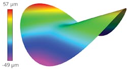
Figure 1 shows an example freeform optic that is used in an unobstructed reflective telescope design. The majority of the surface sag is described by a best-fit sphere, with concave radius ~200 mm over a 100-mm-diameter clear aperture. The remaining form has ~100 μm of mostly asymmetric deviation from this sphere.
The surface was first measured with a custom CGH and a 4 in. f/1.5 transmission sphere. Alignment of the CGH to the interferometer was simple because of the inclusion of alignment features on the hologram. Part alignment, however, was quite tedious. In a traditional sphere test, the alignment errors are X tilt, Y tilt, and power, and the adjustments are basically orthogonal (that is, three alignment knobs will independently adjust each of the tilts and power). The freeform surface alignment, though, includes six degrees of freedom that are not orthogonal, making the fringe nulling operation quite a bit more challenging.
The surface was also measured without null optics on QED's ASI(Q) running prototype freeform software. The basic principle of the test is the same as a non-null stitching test of a rotationally symmetric asphere. Rather than trying to match the reference wavefront to the test surface with null optics, the surface is instead tested against a spherical wavefront. Stitching is required because the vast majority of aspheres have too much aspheric departure from a sphere to be acquired with a single measurement. In this example, a 6 in. f/3.5 transmission sphere is employed, and a lattice of 47 subapertures acquired to adequately cover the part (see Fig. 2a). The part alignment is software-assisted, and the subapertures are acquired and stitched together automatically (without user intervention).The two different interferometric techniques agree quite well. Figure 2b shows that the figure error maps qualitatively agree, and scalar metrics such as peak-to-valley (PV) and root-mean-square (rms) also compare favorably.
High-resolution analysis
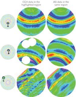
Close examination of the data, however, reveals some subtle and important differences between the measurements. For the next analyses, we removed a 36-term Zernike polynomial fit from each map to remove the low-order form and highlight mid-spatial frequency features on the surface. One difference between the two maps is the number of resolution elements: subaperture stitching enables more magnification than the full-aperture CGH test. In this example, the stitch test has 2000 pixels across the diameter of the surface, while the CGH test has 600. The impact of this is apparent if we zoom in on a 10 mm region on the part: the features in the stitched map are much sharper (see Fig. 3).Lateral distortion
Lateral registration and local magnification is another consideration with interferometry. Spheres, aspheres, and freeforms cannot be projected onto a plane without some form of distortion (similar to maps of the earth). For quality assessment, distortion is not of great concern, as it does not materially alter metrics such as peak-to-valley or rms. However, for deterministic correction of a surface, distortion can be quite important since it is important to know where a feature is to correct it.
The typical interferometer mapping assumption is a direct projection to the equatorial plane (analogous to looking straight down at the part). Aspheric null tests, however, often deviate from this assumption, and this example CGH test is no exception.
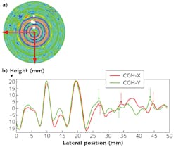
A variable asymmetric (anamorphic) distortion is present that exceeds 2% in some locations. The rings introduced by a diamond turning fabrication step actually make it relatively easy to observe the distortion on this part. The rings should be axisymmetric (corresponding to the diamond tool's cutting path), and thus be located the same distance away from the axis in either the X or Y axis. They actually vary by up to a millimeter in some locations (see Fig. 5).While 3D profilometry/CMM techniques can test a variety of freeform shapes, interferometry is preferred for some optical requirements. A CGH null test has typically been employed in such cases, but the need for a custom dedicated null restricts design and prototyping flexibility.
The ASI(Q) stitching system provides flexibility for plano, sphere, and asphere testing, with now-demonstrated flexibility for freeform surfaces. We show nanometer-level agreement with a CGH test on a sample freeform, and achieve even better lateral resolution. Subaperture stitching lacks the ghosting and other diffraction artifacts in a CGH that can corrupt mid-spatial frequency estimates. It also simplifies treatment of the oft-forgotten alignment and distortion correction steps that can bedevil metrology technicians.
ACKNOWLEDGEMENT
ASI(Q) is a trademark of QED Technologies.
REFERENCES
1. K. P. Thompson, P. Benítez, and J. P. Rolland, Optics & Photonics News, 23, 9, 32-37 (2012).
2. T. Köhler, C. Schindler, and E. Roth, "Mastering the art of freeform optics manufacturing," OptoNet Ultra Precision Manufacturing of Aspheres & Freeforms Workshop, Jena, Germany (Sept. 21, 2016).
3. G.W. Forbes, Opt. Express, 20, 3, 2483-2499 (2012).
4. G. Derst and V. Giggel, "Fabrication technologies for large optical components at Carl Zeiss Jena GmbH," Proc. SPIE, 7739 (2010).
5. M. Beier et al., "Fabrication of high precision metallic freeform mirrors with magnetorheological finishing (MRF)," Proc. SPIE, 8884 (2013).
6. T. Blalock, K. Medicus, and J. DeGroote Nelson, "Fabrication of freeform optics," Proc. SPIE, 9575 (2015).
7. P. Murphy, J. Fleig, G. Forbes, D. Miladinovic,and G. DeVries, "Subaperture stitching interferometry for testing mild aspheres," Proc. SPIE, 6293 (2006).
About the Author
Chris Supranowitz
Senior Applications Engineer, QED Technologies
Chris Supranowitz is a senior applications engineer at QED Technologies (Rochester, NY).
Paul Murphy
Senior Optical Engineer, QED Technologies
Paul Murphy is a senior optical engineer at QED Technologies (Rochester, NY).


