Machine-vision technology is expanding rapidly into areas as diverse as collision avoidance and agricultural-produce inspection. The speed and accuracy available with such automated inspection systems allows end users to make real-time accept-and-reject decisions and also perform process control by measuring critical dimensions. While charge-coupled-device (CCD) cameras and structured light will still work best for many inspection and process-control applications, laser scanning can, at times, complement existing machine-vision technology and even provide superior vision in certain imaging niches.
Applications for which inspection systems based on laser scanning fare well include those where ambient lighting is not ideal, the item inspected is light sensitive, and highly polarized light or narrow wavelength bands are required to increase contrast. The technology also has an advantage over other options when a large number of pixels are desired and when fluorescence imaging is used. Properly equipped laser-scanning equipment can see through rain or fog that would blind conventional camera systems.
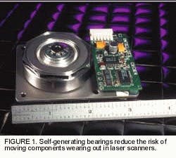
One possible scanning drawback is moving components that could wear out. This risk, however, has been significantly reduced with the introduction of long-life self-generating air bearings that do not wear in operation because there are no physical contacting surfaces. Scanning systems also are more compact than in previous years (see Fig. 1).
Inspection in two dimensions
Machine-vision systems based on laser scanning can be used in two-dimensional (2-D) and three-dimensional (3-D) applications. In 2-D applications, the inspection device uses a rotating polygonal scanner or galvanometer to produce a scanning spot. The second axis of the raster is produced by either object motion or by a secondary scanning device such as another galvanometer. The scene is interrogated pixel by pixel, line by line, serially. A CCD camera system, by comparison, views the scene in a parallel fashion and extracts scene information serially. These cameras also now use many output taps to increase readout speed.
null
One 2-D application for which CCD cameras and laser-scanning systems compete involves the inspection of continuously moving webs of material. Both techniques allow inspecting webs on the fly by freezing image motion. While linear-array CCDs perform well, their costs climb rapidly if the application requires the vision system to provide more than 2000 pixels across the web.
Laser scanners can often provide up to 25,000 pixels across a web at high speeds, while staying cost-competitive (see Fig. 2). There also is flexibility to set up systems to scan various web widths with user-defined pixel sizes or select laser wavelength to optimize imaging and avoid light interaction with the material being inspected, such as film. In addition, users can design the light-collection method to allow acquiring images by specular reflection, diffuse reflection, fluorescence, transmission, or a combination of these techniques.
Because of this capability to control laser parameters, the scanning technique is well suited to interrogating developed film pixel by pixel. One application involved creation of a custom vision system to digitize film images from 70-mm film. Because the film was in a continuous web form, the web scanner used a polygon to generate one axis of scan and a film transport to provide the second. This system was designed with a helium-neon laser as the interrogation source. A collection-integrating cylinder gathered the diffusely transmitted light, and detectors located at each end were summed to produce the signal.
FIGURE 2. Unlike CCD cameras, laser scanners can provide up to 25,000 pixels across a web of material to be inspected, even at high speeds. Systems can also be set up to scan various web widths with user-defined pixel sizes.
One challenge is that the system had to operate from an optical density of 0-3, and small amounts of stray light would negatively impact data integrity. To reduce the optical scatter emitted from the laser, system designers used spatial filtering. The requirements for low scatter off the polygon also prohibited the use of diamond-turned optics, which can be produced with a surface finish approaching 50 ? rms (root mean square). This limited designers to conventionally polished nickel-plated aluminum polygons, for which a finish of less than 15 Å rms is typical.
The finished scanning system was able to interrogate the film to 8-bit-digitize the images at a 2-MHz data rate. A lens turret allowed its operators to use four different spot sizes, with polygon and film transport speeds changing automatically to maintain the proper pixel aspect ratio and data rates.
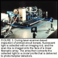
Another good application for laser scanning is conveyor-based 2-D inspection. When inspecting printed-circuit boards (PCBs), for example, machine vision can eliminate the fatigue factor associated with inspectors looking at large numbers of bare boards. One particular laser-scanning application of this type required the inspection of bare 18 ? 24-in. printed-circuit panels at 1-mil resolution for a variety of defects, including opens, shorts, and narrow or missing traces. The system developed for this application used fluorescence to gather information, with the 488-nm line from an argon-ion laser being scanned across a board in a 4-in.-long swath. The 488-nm wavelength was used because PCB substrates fluoresce when exposed to it, providing good contrast that could not be achieved with conventional lighting and CCD arrays (see Fig. 3).
null
Three scanning heads work in parallel to increase inspection throughput. The acquired image is then delivered to the system and evaluated based on established design rules and database comparison techniques.
Seeing in 3-D
While 2-D systems make up the majority of machine-vision applications, 3-D machine vision captures the public's imagination. Examples include robots that coordinate their movements via machine vision and automobiles that see and react without the need for steering input.
In the 3-D environment, laser scanning will incorporate many of the features of 2-D scanning and add a third dimension through various techniques, including confocal imaging, triangulation, or time-of-flight measurement. Laser scanning will work at the microscopic and midrange inspection ranges, with long-range work possible if appropriate technology switching is incorporated.
At the microscopic level, laser scanning is used in scanning confocal microscopy. Systems acquire images by imaging back through the optical system and using an aperture to define the image plane. The sample is stepped through focus, and the reimaged object is observed. The device continues taking 2-D slices through the object until the 3-D representation is built.
At working distances of 0.1-5 m, the most common method of ranging involves CCD cameras with structured lighting. Machine-vision applications in this range that are based on laser scanning, however, use laser triangulation to obtain the third dimension. These devices typically incorporate both a laser scanner and a linear CCD array. The laser sends out a narrowly defined beam, and a tilted linear array senses the third dimension. The equipment will scan both the linear array in the slow-speed axis and the outgoing beam to preserve the triangulation angle and the detector focus. This approach works in environments where ambient lighting forces the instantaneous illumination to be large to overcome integration of the ambient light noise.
The technology of choice
For equipment that must view objects further than 3 m away, there is some overlap with the laser-triangulation technology of the midrange systems. The technology of choice is either laser pulse timing or a phase-shifting technique. Pulse timing uses a short-duration laser pulse and high-speed clock to determine distance based on the time of flight of the laser pulse from the emitter to the object and back. Phase detection uses a laser with a high-modulation frequency to determine phase difference between the output signal and the signal returned from the object. This difference is related to the time delay caused by the time of flight. One problem with the phase-detection technique is the ambiguity that can arise when multiple cycles are involved, so devices also use a second modulation frequency.
Both pulse timing and phase shifting can operate up to very long ranges. Pulse timing, in particular, can work well in inclement weather conditions with proper wavelength selection and rejection of backscatter from atmospheric effects that are outside the time-capture window. One long-range laser-scanning application required a device to obtain an image within an 8-m cube. The system used an infrared laser diode as the source and a polygon and galvanometer mirror for scanning in x and y axes. The output and collection apertures were separated on the optics to minimize backscatter effects.
To obtain the z axis, the system measured the time between an output pulse and the reception of the backscattered pulse from the scene. Because the output and return apertures were separated, the system required alignment so that the collection aperture would be sized just large enough to always include the laser spot, yet still minimize ambient light pick up. The scanning device produced a 3-D raster map of 100 x 100 pixels with 1-cm depth resolution. Scanning the scene required a 1-s cycle time.
In essence, throughout the microscopic to long-range machine-vision applications, systems integrators will continue to rely heavily on CCD cameras as the front end of vision-based inspection solutions. Laser scanning will offer an alternative that can extend vision capabilities when its unique features fit well with the applications.

