An optical scanner is a key beam-steering component in systems for analyzing or synthesizing an image. A scanner can follow a predetermined or controlled pattern in systems relying upon light as a medium that conveys information; laser light is used in many applications, but several, especially entertainment, use white-light lasers. Some infrared scanning systems, which will not be discussed here, rely upon thermal effects to translate information onto film.
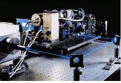
Most scanners use mechanical actuation to move light; galvanometric and resonant scanners are the most common. An acousto-optical (AO) scanner, however, changes the direction of the light as a function of the change of its frequency. Scanning processes follow an internally generated raster or vector pattern, and some scanners can also create images by responding to an external signal (see Fig. 1).
This Product Focus reviews some of the alternative methods of scanning for image creation or replication. Application-specific solutions are a key aspect of this technology; this article will survey several of the newer applications and touch upon some of the more traditional ones (see Laser Focus World, June 1994, p. 57). A partial listing of manufacturers of optical scanners follows on p. 104. A more complete listing is available, in several sections, in the 1996 Laser Focus World Buyers Guide, beginning on p. 262.
Plane-mirror scanners
Galvanometric scanners use an electromagnetically driven motor to steer a light beam in a particular pattern. The plane mirror, frequently coated to enhance its reflectivity, that directs the beam is mounted on the armature of the motor with the reflective surface parallel to the axis of rotation of the armature. There are three types of armatures--moving coil, moving iron, and moving magnet. Each provides performance trade-offs to the user and can be used for either vector or raster scanning. Galvanometers can position beams over a wide (up to 80°) angular range at speeds ranging from hundreds of microseconds to milliseconds with microradian accuracy. When integrated in systems, their capabilities include flexible, controllable, and programmable beam steering. These features are useful in laser display and entertainment, material processing, laser machining and micromachining, and rapid-prototyping applications in which the beam pattern may need to be varied.
Resonant scanners differ from galvanometers in that the mirror is not steerable; vector scanning is not possible. Instead, the armature and mirror assembly, also known as the rotor, oscillate at the natural angular resonance. These devices have many applications for which raster scanning is important. These systems are concerned with issues of pixel placement, resolution, scan rates, and large angular excursion (a wide scanning angle). In addition, because of the types of systems in which resonant scanners are mounted, system designers are especially concerned about minimizing wobble and avoiding the transmission of vibrations into other parts of the system.
Acousto-optic scanners, also known as acousto-optic beam deflectors (AOBDs), can be used to control the position of a laser beam. The output of AOBDs can be either a line scan or random vector scan, depending upon the configuration of the driving electronics. For a continuous linear scan, the electronics consist of a linear voltage-controlled oscillator that drives a radio-frequency amplifier, causing it to emit a frequency- modulated signal. To produce a vector scan, the electronic input is converted from a digital signal to an analog signal, which is used to drive the voltage-controlled oscillator. With this kind of electronic input, the AOBD deflects the laser beam to a specific point in the output plane.
Material selection is an important aspect of the optical element. A variety of materials can be used, including tellurium oxide, lithium niobate, germanium, fused quartz, and special flint glasses. Other factors in an AO system include the fly-back time, defined as the time it takes to fill the AOBD plus the electronic retrace time, and the lensing effects, that in some configurations require the use of cylindrical lenses to correct the shape of the output beam.
Acousto-optic beam deflectors can be used to create two- and three-dimensional scanned projections. Two independent AOBDs, mounted with their longitudinal deflections orthogonal to each other and driven independently, will create a two-dimensional scanned image.
A different approach is used to create three-dimensional imagery of computer-generated images. The system uses a three-color laser subsystem for generation and a helical display assembly for positioning spheres or points of light within the display volume (see Laser Focus World, Oct. 1996, p. 45). A computer-based controller prepares the data and generates the modulation and deflection signals to move the scanner. The system can take information from an autoCAD interface or from a three-axes space. Such displays are well suited for computer-aided design and computer-aided manufacturing (CAD/CAM) applications, air traffic control, and, of course, military applications where three-dimensional information is essential.
Spinning mirrors
Polygon mirrors are another way to scan a light beam (see Fig. 2). A polygon mirror has a number of plane-mirror facets parallel to and facing away from a rotational axis, which is usually the shaft of the motor. The shaft spins, and the polygon mirror rotates at speeds up to 120,000 rpm with an ac motor. If higher rotational speeds are required, gas-turbine motors will spin the mirror faster. However, gas-turbine motors have short duty cycles and are much more expensive than ac motors.Polygon scanners are usually rotated continuously in one direction and provide very fast scanning rates and wide scanning angles (as much as 360°), as well as velocity and rotational stability. Because of the inertia of the motors and the scanning assembly itself, these systems are not practical in applications that require rapid changes in scan velocity or direction or that must operate in a stop-and-start format. Polygon scanners are commonly used in nonimpact computer printers, graphics facsimile machines, and laser inspection systems.
There are other types of polygons such as irregular polygons, which have a number of plane-mirror facets but at a variety of angles with respect to the rotational axis. These mirrors cost more to manufacture. The benefit of irregular-polygon mirrors is the creation of a nonsuperimposed repetitive scan. A point-of-sale scanner that reads the universal product-code symbols is an example. The most important consideration is the need to continue to maintain diametric symmetry so that dynamic balance is possible.
A more compact scanning mirror is the inverted polygon, with the mirrors on the inside face--the surface that faces the rotational shaft. This design is not as dynamically stable, requiring that it be rotated much more slowly than regular polygons.
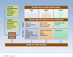
There are a number of design considerations that must be reviewed before a particular scanner is selected (see Fig. 3). The first, sizing the optical system, is determined by the beam, its qualities, and attributes. Next comes choosing the type of image generation: step, raster, or vector. Further considerations involve the scanning speed and positioning accuracy. Each choice opens other options which in many cases are custom solutions.Technology drivers
In the applications already noted, almost all the scanners go into another manufacturer`s piece of equipment; the packages are designed for the OEM market. Cost is a primary driver for these fabricators, so volume manufacturing techniques, economies of scale, and reduced costs for materials and processes all play important roles in the successful acceptance of new scanning technologies.
Changes in other industries have also created opportunities driving improvements in the scanning field. Digital logic systems have increased in capability, increasing to a 20-bit word. And improvements in scanning accuracy dictate higher optical resolution, faster scanning speeds, larger apertures, and lower levels of wobble and jitter, even as the system subassemblies get larger.
As is true in many laser-related industries, users neither want nor can afford to be experts in the purchased technologies. They thus require manufacturers to build the components into tested subassemblies. In some niche markets, several manufacturers have built stand-alone products around their core technologies.
Applications
Scanners have become integrated into many commercial and industrial applications. In addition to printing uses already mentioned, scanners are featured in check-processing systems for banks--capturing a coded image on-the-fly and transferring it to microfilm. Several image-archiving applications, including some x-ray and magnetic-resonance imaging processes, are skipping the wet-chemical developing process and going directly to film, using scanners to transfer the image. Similar shortcuts are also being implemented in the quick-print graphics markets.
There are other medical uses for scanning, especially in the dermatological and ophthamalogical fields. Confocal microscopy uses scanning techniques to perform an analysis of biological samples. Scanning is used in the rapid-prototyping of CAD-created parts and in inspecting for defects of wafers and circuits, as well as marking wafers, chips, and other electronic parts at the completion of manufacturing.
These are only a few applications that have shown some degree of commercialization. Many new uses for scanners are surfacing regularly as lasers and optoelectronics penetrate more industries. The choices between scanner types involve many trade-offs; the engineering staffs at the manufacturers are expert in helping a new user work through the alternatives to develop an optimal solution for the latest application.
Diana Zankowsky | Contributing Editor
Diana Zankowsky was a contributing editor for Laser Focus World.


