Laser scanners enhance electronic imaging systems
Laser scanners enhance electronic imaging systems
Scan engines withlaser sources illuminate objects in a raster
fashion to permit high-resolution confocal imaging.
Robert T. Milkowski and Gregory C. Loney
It is becoming increasingly apparent that laser technology offers advantages in electronic imaging applications. At present, charge-coupled-device (CCD) cameras used in conjunction with various types of frame-grabbers are the industry standard for electronic image capture and storage. Because coherent sources offer spatial and wavelength selectivity, however, laser-based imaging systems are becoming a strong alternative as imaging applications demand ever higher resolution.
Laser imaging systems with scan capabilities have advantages over CCD-based and white-light microscopy systems, including enhanced contrast. With the addition of confocal optics, laser-based systems can also perform three-dimensional metrology. Recent laser-based scanning applications include nerve-fiber analysis and semiconductor inspection.
Technology overview
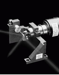
Scan engines raster a source over an object to create an image. General Scanning Inc. (GSI, Watertown, MA) has developed the Video Scan Head (VSH), a scan engine for use with real-time laser point-scanned image-capture systems. Suitable for use with continuous-wave and pulsed lasers, the x-y scan head consists of a GSI 4- or 8-kHz counter-rotating scanner and a moving-magnet galvanometer. A mechanical sub-system orients the mirror shafts perpendicular to one another to form a two-axis scanning system (see Fig. 1). Mirror coatings on the standard VSH are suitable for source outputs ranging from 480 to 900 nm; with appropriate choice of coatings and substrates, sources operating outside of this range could be accommodated.1
The counter-rotating scanner provides the horizontal (line) scan, while the moving-magnet galvanometer provides the vertical (page, frame) scan. Line rates are fixed at 4000 and 8000 l/s. Currently, VSH engines can produce frame sizes as large as 1024 1024 pixels and frame rates up to 100 frames/s in a unidirectional mode. Higher-resolution frame sizes are possible and should become commercially available in the near future.
A pixel clock, a counter-rotating scanner driver, and a moving-magnet galvanometer and servo-controller with feedback loop are included with each VSH. Because the counter-rotating scanner is a resonant mechanical device, it produces sinusoidal spot motion. To correct, or linearize, this sinusoidal scan, the pixel clock is phase-locked to the scanner and adjusts the clock rate to match the sinusoidal velocity. The pixel clock provides a signal that sends the image-acquisition device the active pixel timing.The result is a linear, high-fidelity ramp scan. Due to its linear characteristics, the center 88% (?44% of zero crossing) of the scan amplitude is the only region used to acquire data. The number of pixels, pixel enables, a user-defined line, the number of lines per frame, and field size are user programmable.
The system includes a zoom feature that can adjust real-time field sizes to 1/10th of full frame with no loss of resolution. Based on servo offset, these zoomed fields can be panned within the maximum field of view. This pan-zoom capability is unique in that small portions of the whole field can be imaged sequentially without any moving optics or mechanical x-y stages. For example, if the bases of an imaged baseball field were the inspection targets, small imaging subfields could be used to examine each base individually without imaging the rest of the field. This would eliminate both the time required to capture the whole baseball field and the storage space necessary to hold irrelevant image data.
With a laser scanner system, images can be captured by a sensitive point detector. With scanner-based systems, image pixels are produced sequentially by software-controllable scanner position rather than being gathered from fixed-location detector pixels, as in CCD-based systems. A coherent source beam illuminates only one point on the object at any particular time, and the detector measures the reflected light from the object. Interface software maps these data to a pixel in the final image frame. The light source is then scanned to a new location; the measurement process is repeated point by point until the frame is completed.
Confocal imaging
Laser scanning can produce digital images from confocal microscopes. In comparison with conventional white-light microscopes and scanning electron microscopes (SEMs), confocal microscopes offer increased sample depth discrimination and enhanced contrast. Confocal systems can also view thick specimens or materials that cause a high degree of scattering, advantages that have led to the increased use of these systems in biological and materials sciences.
A system is defined as confocal on the object if a point source and a point detector are imaged to the same object point. Consider such a system fitted with a detector behind a pinhole. Light energy scattered from the surface of the object is detected through the pinhole, which filters out stray light returned from above or below the plane of interest. Because the object is imaged pointwise, the return from even a weakly reflecting object point is not swamped by glare from neighboring segments. Confocal systems thus produce high-contrast images; because images are produced using only the light from the confocal object point, the systems also yield extremely accurate z-axis data for capturing surface morphology.2
Certain tissues, such as retinal nerve fiber, can change the polarization of an incident laser beam during interaction. Because they are essentially formed of a collection of parallel rods with diameters less than the wavelength of the incident light, these retinal nerve fibers act as a birefringent medium. The polarization shift induced by such a medium is a function of the optical path length traveled by the beam, so it is possible to deduce tissue thickness with this technique, and from that, to diagnose glaucoma.
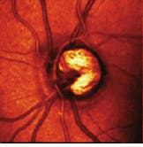
Polarization-shift measurement is the technical basis for the TopSS scanning laser tomography instrument produced by Laser Diagnostic Technologies Inc. (San Diego, CA). A VSH incorporated in the unit raster-scan-illuminates a 15! by 15! patch of the retina with output from a diode laser. Light reflected from the retina is detected and digitized to become one pixel of the 256 256 array making up the retinal image (see Fig. 2). Image capture time is less than 30 ms. In
900 ms, the instrument can produce a full topographic map of the retina, with resolution on the order of 40 ?m; in the macular region of the eye, resolution improves to 2 ?m. The instrument captures features invisible to the human eye and can be used to detect a broad range of retinal conditions.
Contamination defects in semiconductor devices account for an estimated 80% of yield loss. The diameters of contaminating particles decrease as the printed feature sizes decrease, necessitating high-resolution device-inspection systems. Particle-analysis systems incorporating SEMs can inspect unpatterned semiconductor wafers up to 200 mm in diameter for particles as small as 0.16 ?m. To offer this resolution, the SEM must operate at 2000X magnification, limiting the field of view to approximately 50 50 ?m. This increases the time required for inspection and reduces unit throughput.
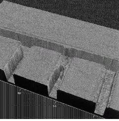
Ultrapointe (San Jose, CA) has developed a particle analysis system with a VSH-engine-based confocal scanning laser imager that maps the defects on the wafer surface prior to the SEM inspection (see Fig. 3). The map pinpoints the location of defects for subsequent SEM analysis, saving time and eliminating the constraints imposed by the limited field of view. Because the confocal system can produce high resolution images of the defects, SEM inspection can often be dispensed with entirely, further streamlining the process. n
REFERENCES
1. G. C. Loney and M. E. Beach, OImaging studies of a real-time galvanometer-based point scanning systemO, to be presented in conference #2665 at Photonics West O96 (San Jose, CA).
2. G. C. Loney, OScanner component and head development for confocal microscopy using moving mirror technology,O Proc. SPIE 1987 (1993).
FIGURE 1. Counter-rotating scanner and a moving-magnet galvanometer are mounted with the mirror shafts perpendicular to one another to form a two-axis scanning system for laser imaging applications.
FIGURE 2. Confocal laser tomography system incorporates laser-based engine to produce high-resolution image of a human retina.
FIGURE 3. Semiconductor inspection system maps defects on wafer
surface with confocal laser imaging system.


