ADAPTIVE OPTICS: Turbulent surveillance—or how to see a Kalashnikov from a safe distance
GLEB VDOVIN, MIKHAIL LOKTEV, and OLEG SOLOVIEV
Long-range surveillance has numerous military, security, and navigation applications. One example from current news: It is critically important to distinguish a Kalashnikov assault rifle from a paddle in the hands of a suspected pirate, when the potential danger is still far away.
At first glance, the problem can be easily solved. Indeed, physics tells us that we should see a 1 mm mosquito at a 1 km distance with a 50 cm telescope. Although a bit bulky, such an optic is not rare even among amateur astronomers. However, a practical experiment would disappoint: The insect will remain invisible for any size of the instrument. Moreover, quite frequently, a much larger object-an apple, a firearm, or a human face-will remain unrecognizable at a long distance.
The resolution is limited by the air turbulence. According to the Kolmogorov turbulence model, solar radiation is absorbed over large areas, creating large-scale hot air movements. These movements scatter to some smaller-scale eddies and vortices, and the process scales down until the temperature differences are finally equalized in the so-called inner scale of turbulence.
The refraction in air depends on the temperature, so randomly changing distribution of the refraction index in the turbulence is optically seen as a blurry veil, preventing sharp imaging. Since most heat exchange happens near the ground, the strongest optical turbulence is observed in the boundary layer, just several meters over the ground, with even stronger turbulence over the areas that are subject to direct sunlight.
It is quite common to characterize imaging through turbulence with a single parameter, r0. This parameter is defined by the largest aperture size that still provides near-diffraction limited imaging in the turbulent conditions. In astronomy, when observation is conducted through a relatively thin turbulent layer from the surface up through the atmosphere, the usual value of r0 is in the range from 5 to 50 cm. However, horizontal imaging on a sunny day can easily result in r0 of several millimeters, even for relatively short observation distances on the order of 1 km.
In a typical horizontal imaging scenario, both the optical aperture and the object size are usually much larger than the r0 (see Fig. 1). The light bundles emitted by different object points go through different volumes of turbulence, resulting in statistically uncorrelated phase distortions for different object points, also called anisoplanatism.1 The distortions are correlated within a small isoplanatic angle, that has the order of magnitude of r0/L where L is the distance to the object, and the area of isoplanatic imaging, with the dimension of ~r0 called isoplanatic patch.
In the close vicinity to the aperture, all ray bundles pass through the same turbulence and the wavefront distortions introduced in this volume can be considered isoplanatic. To complicate the situation even further, not all wavefront distortions created by the turbulence reach the aperture. In the far field, the isoplanatic patch is not resolved by the optic, and the turbulence introduces geometric distortions and warps in the otherwise sharp image.
Correcting for aberrations
Adaptive optics (AO) is the first choice technology for correction of dynamic optical aberrations. It can be directly applied to the isoplanatic aberrations, introduced in the optical system itself, and in the close vicinity to the aperture, where the turbulence is still isoplanatic.
There are two ways to control the AO system: phase conjugation and optimization. Phase conjugation needs a bright point-like source for wavefront measurements. In astronomy this purpose is served by a natural or an artificial guidestar. Unfortunately, in horizontal imaging, there are very few scenarios when the object provides optical point-like reference to the observer. The problem of reference can be solved by correlation tracking of the chosen object feature; however, for correct sensing, the size of the feature should be smaller than the isoplanatic patch and the isoplanatic patch should be resolved by the optical system. This condition limits the number of usable scenarios.
As an alternative, optimization relies on real-time trial and error search for the shape of the wavefront corrector that maximizes the quality metrics in the image; for example, the image sharpness. Although it does not need any specific reference, the real-time optimization requires a very fast wavefront control to be coupled to a very fast registration of the probe images-tens of thousands of frames per second is not the limit. Since the camera frame rate is limited by its sensitivity and the available light, the applicability of real-time optimization is mostly restricted to some special situations with very bright sources.
If the object size is large and the turbulence is strong, the weight of the isoplanatic correctable component will be close to negligible, and the performance of AO can be found insufficient to justify its extra complexity. The AO performance can be improved by correcting only the wavefronts emitted by a single point of the object, realizing so-called "foveated" imaging (the fovea is the part of the retina that provides the sharpest image).
Generally speaking, foveated AO correction amplifies the aberration and fuzziness of the remaining image outside the isoplanatic patch. Furthermore, the size of the isoplanatic patch can be smaller than the resolution limit of the optical system, making the AO correction essentially useless.
In theory, the problem of a wide-field AO can be solved by a multiconjugate (volume) corrector with the refraction index volumetric distribution conjugated to that of the atmosphere. However, at the present time, the authors have no information about the existence of such a corrector. Even if it exists, control of volumetric phase represents an enormous technical problem.
System design
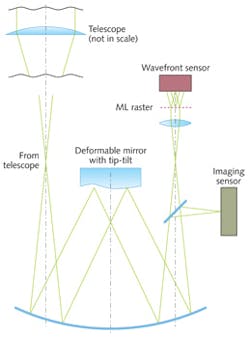
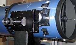
The optical scheme of a portable AO system that has been designed to correct the turbulence on a small telescope is shown in Fig. 2. An achromatic mirror system based on a modified Offner configuration re-images the telescope pupil to the OKO deformable mirror, specially designed to correct for atmospheric turbulence. The mirror combines the ability to correct all Zernike terms up to the third order, with an integrated tip-tilt stage to compensate for image shifts.The complete unit, mounted on a 10 in. Newton, can be operated with an integrated Shack-Hartmann wavefront sensor controlled by the OKO FrontSurfer software either in the phase conjugation mode or in the optimization mode based on the real-time optimization of the image quality (see Fig. 3).
To achieve uncorrelated input data, the observation should be done through different realizations of the turbulent atmosphere, by introducing delays between frames, or by splitting the pupil of the optical system to create multiple images through different turbulent paths.2 Since a number of images are registered simultaneously, the system with multiplexed pupil allows for real-time imaging of moving objects, while the single-pupil time-multiplexed imaging introduces pipeline delay and cannot deal with moving objects. Figure 4 shows different implementations of the multiaperture system:
The direct solution (a) is represented by a number of identical optical systems.
A multiplexed pupil (b) features a microlens raster positioned in the pupil image for splitting the image field into a number of independent images obtained through different turbulent paths.
A plenoptic optical system (c) enables images through different turbulent paths to be obtained from the four-dimensional light field registered by the sensor.
In all cases, the size of the subaperture should be kept comparable to r0 and follow the changing turbulence. This can be achieved by using zoom lenses in configurations a and c, and by changing the microlens arrays in the pupil plane for configuration b.
Multiframe processing methods are numerous and include variants of multiframe selective image fusion3, applicable to the image distortions and warps in the far field, and deconvolution methods, applicable to the phase distortions. Deconvolution methods include blind deconvolution, deconvolution from the wavefront sensing, the Knox-Thompson method, bispectrum imaging, and variations of speckle imaging including methods based on projection on convex sets.4 Regardless of the method, the optical system for multiframe processing should meet the following conditions:
The input pupil should be in the range of 1 . . . 5 r0. This range provides relatively high probability of obtaining a lucky image5, realizing optimal resolution of the system including the aperture and the turbulence.
A number of uncorrelated images should be collected to mitigate the turbulence effects by multiframe processing. Either temporal or spatial multiplexing can be used to obtain these images.
In practice, with a small aperture the observable size of the isoplanatic patch can be much larger than predicted by the theory, because by limiting the aperture we also limit the maximum phase difference between any two aberrations produced by different object points.
If the sensor has a fixed pixel size, the system aperture and focal length should change adaptively in proportion with the turbulence scale r0.
Synthetic approach
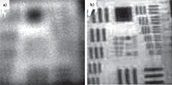
Although stronger turbulence would result in somewhat less detailed images, adaptation will keep the resolution of the system in the quasi-optimal range for the present conditions. Figure 5 illustrates the resolution gain obtained with the combination of adaptive optics and multiplexed imaging in an experiment through conditions of medium turbulence on a 2 km horizontal optical path.We can conclude that no single technology solves the problem of horizontal imaging through atmospheric turbulence. A synthetic approach combining adaptive optics; real-time adaptation of the system parameters, such as the pupil size and the focal length; multiplexed imaging; and digital real-time processing solves the problem to some extent.
With this approach, significant improvements can be achieved in terms of a higher probability of obtaining a good image at a given moment of time, but no method can guarantee that a perfect image will be obtained at any time, especially when the turbulence is strong. There is considerable room for development and improvement in any of these directions.
REFERENCES
1. D.L. Fried, "Anisoplanatism in adaptive optics," J. Opt. Soc. Am., 72, 52–61 (1982).
2. M. Loktev, O. Soloviev, S. Savenko, and G. Vdovin, "Speckle imaging through turbulent atmosphere based on adaptable pupil segmentation," Opt. Lett., 36, 14, 2656–2658 (July 2011).
3. M.A. Vorontsov and G.W. Carhart, "Anisoplanatic imaging through turbulent media: image recovery by local information fusion from a set of short-exposure images," J. Opt. Soc. Am. A, 18, 6, 1312–1324 (2001).
4. A. Pakhomov and K. Losin, "Processing of short sets of bright speckle images distorted by the turbulent earth's atmosphere," Opt. Comm., 125, 5–12 (1996).
5. D.L. Fried, "Probability of getting a lucky short-exposure image through turbulence," J. Opt. Soc. Am., 68, 12, 1651 (1978).
Gleb Vdovin is director, Mikhail Loktev is senior associate, and Oleg Soloviev is senior associate at Flexible Optical, Polakweg 10-11, 2288 GG, Rijswijk, the Netherlands; e-mail: [email protected]; www.okotech.com.


