ROBERT W. SPRAGUE, BORIS SHNAPIR, and GEORGE L. MINOTT
Optical-interference filters of various types are routinely used to transmit, reject, or reflect radiation. Some common filter types include bandpass, shortpass, longpass, and notch filters. A notch filter is typically used in applications that require effective reflection or rejection of electromagnetic radiation within a selected spectral region while providing high transmission at wavelengths outside of the region being rejected.
A particular type of notch filter known as the rugate notch filter offers some clear performance advantages over those made with other technologies. Notch filters based upon the principles of optical interference can be fabricated using rugate, dielectric stack, and holographic technologies. Each of these technologies has advantages and disadvantages when viewed in terms of performance.
Notch filters made with discrete layers can achieve high rejection within the reflection band, high transmission outside the reflection band, and offer excellent environmental durability properties. This type of notch filter, however, suffers from the presence of harmonic structure, which can severely limit the transmission band. Holographic notch filters can show both deep rejection within the reflection band and high transmission outside the reflection band without the presence of harmonic structure. Because of the photographic nature of the holographic-notch-filter manufacturing process these filters can be readily fabricated on complex shapes. Such filters, however, are mechanically less stable and environmentally less durable than filters constructed with materials used in thin-film filters.
Rugate notch filters
Notch filters made with rugate technology can offer all the performance attributes associated with holographic notch filters, with the exception that complex shapes and very large areas are difficult to fabricate.
Rugate notch filters are broadly tunable and many notches can be combined into a single structure to achieve very broad band rejection, multiple narrow notches, or a combination thereof.
They can be designed for use at any incident angle. The level of polarization splitting at large incident angles is similar to that obtained with other types of interference filters
Rugate notch filters can operate over a wide temperature range (-200°C to 200°C) without any significant change in spectral characteristics and can withstand temperature excursions to as high as 400°C without damaging the filter.
These filters can be constructed with minimal wavefront distortion, thus making rugate notch filters suitable for use in imaging applications.
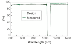
In addition, they can be fabricated in a wide variety of sizes, including miniature sizes; they offer an excellent match of achieved spectral characteristics compared to theoretically derived spectral characteristics; they show extremely robust environmental durability characteristics; and they offer the flexibility to construct more-complex rugate filters involving laminates of multiple rugate-coated substrates, substrates with other thin-film coatings, or selected absorption glasses.
As a class of optical-interference filter coatings, rugate thin films have been in existence for some time. For years, rugates were viewed largely as a laboratory curiosity, lacking the ability to be produced in volume. Such filters can now be produced in large quantity in a deposition system capable of coating multiple, large-area substrates in a single production cycle.
Currently, the center wavelength position can be set anywhere within the visible and near-IR spectral regions, but advances in coating-deposition methods are enabling the center-wavelength position of the notch to be extended into the UV and IR spectral regions.
Rugate theory
In contrast to discrete-layer stacks, which are fabricated as a series of thin layers of alternating refractive index, rugate filters consist of a single layer whose refractive index varies continuously with position perpendicular to the substrate plane. This refractive-index variation is a single sine wave of the form:1
(1)
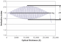
The optical properties of a thin film and the spatial distribution of the refractive-index profile can be thought of as a Fourier-transform pair.2, 3 The above-index modulation transforms into a single reflection peak at λp. This structure has side lobes and hence is not very useful. In order to suppress the side lobes the sine function above is apodized.4 It is also impedance-matched to the incident media and the substrate. One can use a gradient for the impedance match (see Fig. 1).
The index profile represented above produces a single notch. The optical properties of this notch are controlled by four parameters: the average index N0, the amplitude of the index modulation ΔN, the period of the modulation, and the number of periods. The period of the modulation determines the wavelength of the notch. The amplitude of the modulation determines the width of the notch. The number of periods for a given index modulation determines the depth of the notch. Finally, the average index determines the thickness of the coating and its sensitivity to angle.
In practice, average index of refraction is determined by the amplitude of the modulation needed to obtain a specified bandwidth. As these coatings are driven by optical thickness, higher average index translates directly to thinner coatings, lower cost, and minimum angular sensitivity.
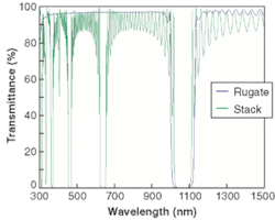
The performance difference between rugate (blue) and dielectric stack (green) fabrication is readily apparent in Fig. 2. The transmission region of the rugate filter is limited only by the materials used in its construction. The dielectric stack design is a simple third-order stack (0.75H 0.75L)12 0.75H. (H stands for high-index material; L stands for low-index material). In this stack, the 0.75H is three-quarter of a wave of high-index material at the design wavelength, and the number 12 indicates the number of times that the two layers are repeated. This design could be improved to reduce the ripple, and methods exist to eliminate the harmonics, at the cost of added thickness and complexity.5Applications
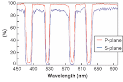
Rugate notch filters are increasingly being used in applications that involve the reflection and/or rejection of more than one line. Rugate notch filters can also be used at nonnormal incidence as dichroic and multichroic beamsplitters (see Fig. 4).Both single and multi-line rugate notch filters, are now being used in sophisticated fluorescence-based spectroscopic instruments. Use of rugate notch filters in the optical designs of these instruments provides performance and cost advantages over use of more conventional optical subcomponents. Rugate notch filters have also been used in Raman spectroscopy applications to separate (by reflection) the incident laser-excitation radiation from the Raman-scattered radiation. These filteers can be fabricated with optical densities greater than can be measured in commercial spectrophotometers.
Other applications include astronomy-related applications that call for high transmission over a broad spectral range while rejecting a narrow wavelength band. These filters can meet the additional requirement of low wavefront error for high image quality.
Rugate notch filters are capable of providing effective rejection within a narrow spectral region, or notch, while providing high transmission over a broad spectral range outside of the notch. Other characteristics such as robust environmental durability and suitability to fabrication in a wide range of shapes and sizes further enhance the attractiveness of this type of filter to designers of optical systems.
REFERENCES
- W. E. Johnson and R. L. Crane, Proc. SPIE 2046, 88 (1993).
- B. G. Bovard, Appl. Opt. 29, 24 (1990).
- E. Delano, J. Opt. Soc. Am. 57,1529, (1967).
- W. H.Southwell and R. L. Hall, Appl. Opt. 28, 5091 (1989).
- B. G. Bovard, Appl. Opt. 32, 5427 (1993).
ROBERT W. SPRAGUE is a scientist, BORIS SHNAPIR is a senior product designer and GEORGE L. MINOTT is manager of the commercial group at Barr Associates, Inc., 2 Lyberty Way, Westford, MA 01886; e-mail: [email protected].


