Astronomers have inferred the existence of more than 120 planets outside the solar system by observing Doppler shifts in stellar spectra induced by planets gravitationally perturbing their parent stars. These observations have been made with Earth-bound telescopes that do not enable scientists to directly see other planets. Researchers at NASA Goddard Space Flight Center (Greenbelt, MD) are investigating the feasibility of building a space-based coronagraphic 1.5-m telescope that would enable NASA scientists for the first time to see Jupiter-like bodies in other solar systems.
Missions of this type could detect and characterize extra-solar gas-giant planets in orbit around nearby stars out to 40 parsecs, or 130.4 light years. If selected, a coronagraphic mission could launch as early as 2009. ASML Optics is supporting Goddard’s efforts to demonstrate the technical feasibility of fabricating suitable optics for coronagraphic missions. One configuration under investigation would include a prolate-spheroidal apodizer matched to a hard-edged occulting mask to attenuate light from the central star, while permitting light from its much dimmer planets to reach the focal plane. Such an approach would allow direct imaging of Jupiter-like planets as close as 0.28 arcsec to their parent star in visible light.
High wavefront accuracy required
The coronagraphic approach requires that the vast majority of the starlight be blocked by the occulting mask, which means that the wavefront error of the system must be very small.1, 2 Otherwise, the faint planetary images are overwhelmed by diffracted and scattered light from the star. Current technology is unable to provide large conventional astronomical optics that meet the required level of wavefront accuracy of less than λ/1000.
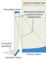
FIGURE 1. The on-axis wavefront error of a large telescope can be corrected by placing a static corrector mirror between the mirror and the image.
One way to address the system wavefront-accuracy problem is to introduce one or more small, static, microfigured wavefront correctors into the optical path to compensate for the errors in the other optical elements (see Fig. 1). The surface of this nominally flat aspheric corrector is figured with the inverse of wavefront errors produced by other elements in the optical path, yielding a system with an acceptably low on-axis wavefront error. Such a scheme also lends itself well to working with other techniques such as deformable mirrors.
Static aspheric optics have not been used to correct mid-spatial-frequency wavefront errors, but conceptually similar elements have been used to remedy low-order wavefront errors in the Hubble Space Telescope and elsewhere.3 Mid-spatial-frequency correctors have only recently become practical as a result of improvements in optical-figuring technology.
To help Goddard demonstrate the feasibility of static correctors for nulling mid-spatial-frequency errors, we have produced a parabolic mirror with a surface figure that produces a wavefront error approximating what might be expected from the uncorrected telescope-approximately 10-nm root-mean-square (rms) over the spatial-frequency range of 3 to 50 cycles/aperture-and a corrector mirror that reduces the wavefront error to less than 0.4-nm rms over that range.
Demonstration
To provide a demonstration of a high-order wavefront correction for coronagraphic systems, we fabricated a two-element, double-pass optical system composed of a 550-mm-focal-length off-axis parabolic mirror with intentional figure error and a nominally flat aspheric autocollimating corrector mirror. Both have clear-aperture diameters of 120 mm. Although nearly flat, the autocollimating mirror has undergone irregular aspheric figuring to correct the system wavefront error.
The corrector is tested within the optical system it is designed to correct, and its figure is adjusted until adequate improvement in the measured wavefront has been achieved. Because of the double-pass nature of the system, the corrective features have approximately twice the magnitude of the errors on the parabolic mirror surface. The targeted wavefront error for the corrected system was chosen to be 0.70-nm rms or less in the spatial frequency range of 1 to 3 cycles/aperture, and 0.40-nm rms or less from 3 to 50 cycles/aperture.
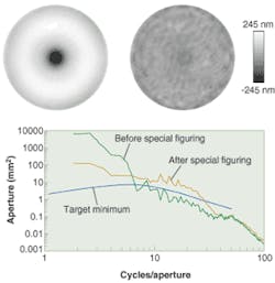
For the demonstration, the parabolic mirror needed to be figured to produce at least 2.9-nm rms of wavefront error in the system at spatial frequencies from 1 to 3 cycles/aperture, and at least 9.7-nm rms of error in the 3- to 50-cycles/aperture range. To achieve the error specifications, a Zerodur blank was prepared as an off-axis paraboloid up to the final figuring step. Rather than reducing all surface errors, the optical surface was given a special figuring step to remove most of the remaining axisymmetric errors and to selectively amplify or suppress the remaining errors as a function of spatial frequency (see Fig. 2).
The final figure error of the parabolic mirror created a double-pass wavefront error well above the minimum specification. Power-spectral-density (PSD) plots of the wavefront error before and after the final figuring step were compared to the nominal PSD specifications. The error has been reduced at the lowest spatial frequencies (mostly by the removal of axisymmetric structure), and increased in the frequency range from 6 to 40 cycles/aperture, yielding a curve well above the guideline target over most of the range.
Fine structure minimized
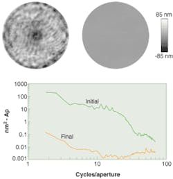
After the parabolic mirror was prepared, the initially flat (nonaspherized) Zerodur corrector mirror was installed in the system and the wavefront error was measured. The results were used to compute the figure adjustments needed to correct the wavefront, and the corrector mirror was figured accordingly. The wavefront was then measured again, and the procedure repeated until the wavefront error was reduced to the required level. The corrector makes a striking improvement in the wavefront, especially with regard to fine structure (see Fig. 3).
FIGURE 3. Initial (top left) and final (top right) maps of the corrected system show the reduction in mid-spatial-frequency content. The PSD of the corrected system (bottom) shows effective correction to higher than 50 cycles/aperture.
As shown by the power spectral density, wavefront improvement in the final system can be seen over the spatial-frequency range from 1 through 50 cycles/aperture and beyond, to at least 70 cycles/aperture. The maximum spatial frequency of the corrector is determined largely by the limitations of the test metrology: test noise and camera resolution limit the effectiveness of the figuring process at high spatial frequencies.
The static microfigured corrector reduces wavefront error from 17-nm rms to below 0.4-nm rms over spatial frequencies from 3 to 50 cycles/aperture. This result validates the potential use of such a corrector to yield a wavefront with an acceptably low level of error for a coronagraph. Possible applications extend to any optical system that requires a wavefront with exceptionally low mid-spatial-frequency error, if there is access to optics where the correction can be applied. Correctors could potentially be fabricated that would provide wavefront improvement up to spatial frequencies several times higher than 50 cycles/aperture.
REFERENCES
- R. Woodruff et al., Feasibility of and Tech. Roadmap for Coronagraphic Approaches to TPF, in response to NASA NRA 01-OSS-04, Extra-Solar Planets Advanced Mission Concepts, Final Report (Nov. 29, 2002).
- R. G. Lyon et al., Proc. SPIE 4860, 251 (2003).
- R. Woodruff and R. F. Cahill, Proc. SPIE 3356, 249 (1998).
ROBERT KESTNER is vice president of optics and CHRIS WITEBSKY is senior research and development engineer at ASML Optics, 3900 Lakeside Dr., Richmond, CA 94806; MARK CLAMPIN is an astronomer and RICHARD G. LYON is a research scientist at NASA/Goddard Space Flight Center, Greenbelt MD 20771; and ROBERT WOODRUFF is a research scientist at Lockheed-Martin Civil Space, Denver CO 80201. Contact Noreen Harned, vice president of marketing and technology at ASML Wilton; e-mail: [email protected].


