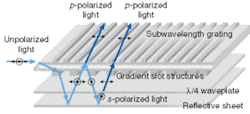
At the National Chiao Tung University (NCTU; Hsinchu, Taiwan), researchers are working on getting more light into a liquid-crystal display (LCD) and distributing it more evenly. They have come up with a light guide that not only takes account of the source position as it distributes the illumination, but also converts s- into p-polarized light, effectively recycling what would have been wasted. An extinction ratio of 10 (p- to s-polarization output) has already been demonstrated and, according to Ko-Wei Chien, who is working on the project, this could theoretically be increased to 25 with the right fabrication technology. As the optics have so far been fabricated using electron-beam lithographic techniques, making large backlights is likely to be a challenge. However, there is no reason in principle why small-screen versions should not eventually be possible.
In the increasingly competitive flat-panel-display market, one of the problems with LCDs is that they waste energy. For large appliances such as computer monitors and television sets that draw power from the electrical grid, this is not a problem. However, for products such as hand-held computers, cameras, mobile phones, and MP3 players, all of which rely on batteries, it is a serious issue. Unlike emissive technologies—light-emitting diodes and lasers—that only create photons as they're needed, LCDs (except under very favorable lighting conditions) require a backlight. Of the photons generated, only about 25% on average are actually available to the user; half are lost because they are the wrong polarization and half are usable but blocked because they are passing through a dark pixel.
The team from NCTU's Institute of Electro-Optical Engineering is attempting to solve the first half of this problem.1 The new device is essentially a planar waveguide that has patterns etched on both top and bottom surfaces (see figure). Light enters through an angled coupler at the side that forces the incoming beam into what would normally be a totally internally reflecting path. A subwavelength grating of dielectric topped with metal is patterned onto the top surface, its orientation perpendicular to the direction of propagation. The grating acts as a beamsplitter, allowing the light that can be properly modulated by the liquid crystal—that with parallel polarization—to be transmitted and the remainder to be reflected.
Not rejected after all
Energy savings result from what happens to the rejected s-polarized light. After reflecting from the top surface, it travels through a quarter-wave plate both before and after reflection from the bottom surface. This causes a rotation in the polarization and the newly converted p-polarized light can pass through the top surface when it next hits. In the experiments done so far, 70% more light has been available to illuminate the display than would have been otherwise. A gain factor of two is theoretically possible and researchers believe that they can approach this by improving the aspect ratio and shape of their grating structures.
Another element in the design is the slot structure between the guide and the polarization-converting layer, used to control the propagation of the light as it travels from the source. By grading the slots—their width decreasing with the distance from the input—light transmission can be gradually increased, the result being a more-consistent output across the display (80% uniformity has been achieved so far).
The researchers are now scaling up the size of display they can work with. Their proof-of-principle experiments have used a grating just 80 × 80 µm in size, with 100-nm grating lines on 200-nm periods. They are currently working at an electron-beam projection facility to produce a 1 × 1-cm grating and have had some good results. If successful, this same technology could give them grating areas of up to 5 × 5 cm. For much larger screens, tiled arrays of gratings may be an option. At the same time, they are working on realizing even-smaller feature sizes for improved p-transmission and s-reflection efficiency.
REFERENCE
- Ko-Wei Chien and Han-Ping D. Shieh, Appl. Optics 43(9), 1830 (March 20, 2004).
Sunny Bains | Contributing Editor
Sunny Bains is a contributing editor for Laser Focus World and a technical journalist based in London, England.
