GREG HOLLOWS
Confocal scanning microscopes were invented almost five decades ago to produce sharper images than are possible with conventional microscopes. They remained just a casual curiosity over the years because of the relatively high cost of producing the special optics they needed. Despite this cost, confocal microscopes benefited many science and technology firms, particularly biologics, in situations in which observing specific pathologies within a precise depth of field is critical. Now newer tools, materials, and techniques allow designers to manufacture these microscopes less expensively and the cost is more in line with the budgets of leading microscope manufacturers.
How it works
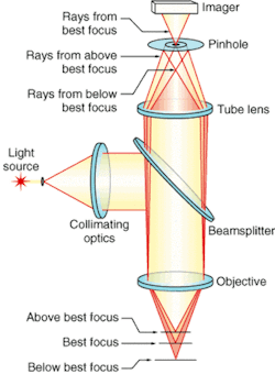
Conventional microscopes project out-of-focus images just above and below the principal plane, which tend to blur the target image. But confocal microscopes eliminate this interference and project all the planes with equal sharpness via a precisely located pinhole in front of the microscope's imager (see Fig. 1).1 The pinhole allows only those light rays emitted from the desired plane to pass onto the imager with high intensity. The area immediately above and below the desired layer comes into focus slightly in front of or behind the pinhole; therefore, most of the light rays transmitted from these areas cannot pass through the aperture and do not reach the imager. The desired image now comes from an extremely thin axial section of the sample because of the small depth of field. Consequently, numerous thin axial sections of the sample can be scanned and the imager can construct high-resolution 2-D and 3-D images that are otherwise difficult or impossible to obtain.
The second critical component of a confocal microscope is the objective lens, which determines the overall resolution of the system. Selecting a suitable lens for a particular application, however, is not as easy as for a conventional microscope. Designers have to understand how to control specific types of aberrations (errors that show up in the final image that are not necessarily present in the original object).
Aberrations arise from the way the optical and mechanical components are designed and made, the effect of other optical components added to the system after the major design work has been completed, and the materials and the composition of the media to be inspected. Aberrations are unavoidable, and although some can be corrected, they are inherent in all optical systems. Chromatic and spherical aberrations are usually the worst types of aberrations.
Chromatic aberration
Chromatic aberration comes from the change in the index of refraction of a lens material as the wavelength (color) of the light passing through it changes (see Fig. 2). The image cannot remain in focus at a fixed location as the wavelength changes. For axial or longitudinal chromatic aberrations, different wavelengths focus at different distances from the lens. The focal length changes with respect to the wavelength. For example, blue light focuses at a point nearer the lens than does green and red, so when focusing a polychromatic system, a colored halo forms around a brighter focused spot. The halo usually appears purple because the blue and red portions of the spectrum defocus and combine.Although the pinhole aperture is the feature that ultimately produces the crisp images, the light intensity diminishes at its focus position in proportion to the wavelength. The perceptible intensity is less than the actual intensity, because not all the light reaches the sensing area. This is not a serious problem in monochromatic systems or those that use a small range of wavelengths. But for a system observing fluorescence across the blue, green, and red spectrums, such as in medical applications, the effect causes the image to deteriorate.
A related aberration, called lateral chromatic aberration, appears as the image moves farther away from the center. Different wavelengths focus to different spot sizes at different distances from the center of the image. They introduce varying levels of intensity and displace color information from the actual position on the object under analysis; lateral chromatic aberrations produce magnification errors. Slight changes in magnification affect the quality of the image and reduce the reliability of critical measurements.
Certain objective lenses can compensate for these shortcomings. Achromatic and apochromatic objective lenses use a combination of different types of glass that allow multiple wavelengths to focus to the same position. An achromatic objective lens works for at least two different wavelengths, while apochromatic objective lenses handle at least three wavelengths.
Even with apochromatic objectives, some systems depend on other optical components such as an eyepiece to correct for chromatic aberrations. Although correcting for multiple wavelengths is important, they become more difficult to correct over a range of wavelengths that are deeper into the UV part of the spectrum.
Laser illumination
Lasers usually provide the illumination for indirect imaging. Compared to multichromatic light, controlling laser wavelength and intensity provide more predictable results. It is also required for imaging in the human biological sciences where fluorescent dyes are used to highlight pathologies.
The objective lens focuses the laser onto the object plane and images the fluorescent dye. Consequently, the laser wavelength also must be considered. System efficiency drops when chromatic aberrations prevent the objective lens from focusing the laser into the object plane, and when materials in the objective lens reduce the overall laser emission or transmission. But adding or changing optical components at the laser can compensate for some of these problems.
A reflective objective lens also compensates for chromatic aberrations because such lenses are not sensitive to different wavelengths. But their resolution is generally lower than traditional refractive lenses, particularly in high-magnification applications.
Spherical aberration
Although better lenses compensate for many aberrations, spherical aberration does not always come from optics. Spherical aberration is similar to chromatic aberration; it arises axially as a function of the distance from the lens and appears laterally across the image. The difference comes from the fact that low-order spherical aberration is not wavelength dependent. Some higher-order spherical aberrations (known as spherochromatism), however, does depend on the wavelength.
Spherical aberration relates to the size of the lens aperture and the position of the object and image. When rays from the object pass through points farther from the center of the lens, the focus point moves farther away from the best possible spot. Thus, not all the light intensity from a given point of the object gets through the pinhole.
However, these aberrations can be corrected. The design of an optimal objective lens depends upon the relative positions of the object and the desired image. Variations in either can adversely affect the visible image because the system is working slightly outside its design parameters.
On the object side, the cover slip, media, and any solution or material under inspection all have an index of refraction different from that of air. The material that the light passes through (located between the object and the first lens element) is considered when designing an objective lens, whether air, water, oil, or another medium. A different medium put between the object and the objective lens looks like one more optical component. This moves the best-focus point and introduces more spherical and other aberrations.
Users also must understand how to prepare and inspect the sample so they can make a more informed decision when choosing the best optics. Changes in solution concentration, temperature, and quality of cover slips and immersion oils must be controlled or repeatability can be compromised.
Finite and infinite conjugates
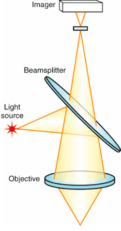
Other factors considered include the beamsplitter that introduces the laser illumination, and other optical components. If not considered initially, they introduce aberrations and reduce image quality. In a system using a finite-conjugate objective (one that focuses the image to a specific distance without other optical components), the negative effects are easily seen. That is, light passing through a beamsplitter, the filters, and other components passes through yet other index changes and not all rays pass through at the same angle. The rays deviate slightly and introduce aberrations that were not found in the original objective-lens design.
Some filters and beamsplitters also reduce the intensity of the light rays, which depends on the wavelength and the angle. The angle at which light at a particular wavelength goes through one of these optical components can affect the transmission level of that ray and reduce transmission at certain wavelengths. This can be detrimental to light-starved systems.
One solution is an infinity-corrected objective lens (see Fig. 3). The difference between an infinity-corrected objective lens and one designed for a finite conjugate is that the former cannot focus an image at a particular distance without a second set of optics called a tube lens.The rays exiting infinity-corrected objective lenses are parallel. When they pass through a beamsplitter or a filter, all rays pass at the same angle and maintain their relative positions, which reduces or eliminates aberrations—even those introduced by the tube lens—and alleviates the problem caused by the angle.
Yet another solution uses objective lenses designed at a finite conjugate and optics added to the systems immediately following the object lens to create an infinite conjugate. This can work well, but the optics can increase the magnification and develop more aberrations if not properly matched to the objective lens.
REFERENCE
- H. Ernst Keller, "Objective Lenses for Confocal Microscopy," Handbook of Biological Confocal Microscopy, ed. James B. Pawley, Plenum Press, NY (1995).
Greg Hollows is imaging-product line manager at Edmund Industrial Optics, 101 E. Gloucester Pike, Barrington, NJ 08007; e-mail: [email protected].


