Researchers at the HiLASE high-power multi-slab laser project, located at the Institute of Physics AS CR (Prague, Czech Republic), along with their colleagues at CNR-IFN (Padova, Italy) and the Czech Technical University in Prague, have created a system that simulates optical aberrations produced by the heating and cooling processes expected within HiLASE, allowing them to optimize an aberration-correcting adaptive-optics (AO) system even though the HiLASE is still under development.1
The HiLASE laser will be built around a ytterbium:YAG (Yb:YAG) multi-slab amplifier that in one configuration will produce 100 J pulses at a 10 Hz repetition rate. This laser will contain many potential sources of optical aberrations of lesser or greater significance. These include static aberrations of optical elements, thermal aberrations occurring in the amplifier slabs, and smaller random aberrations occurring, for example, from the flow of cooling gases in the laser chambers.
The optical aberrations and lowest-order (tilt and defocus) thermal aberrations will be reduced by precisely aligning the optics, then minimized by a one-time adjustment of a deformable mirror. This leaves the higher-order thermal aberrations, which will still need to be corrected.
To discover the proper AO mirror configuration, the researchers first numerically modeled the thermal effects in the HiLASE laser, then created simulated phase maps. The laser can be set up to produce 10 J or 100 J pulses. In the 10 J configuration, the dominant thermal effect will be the absorption of the pump light by the active medium, producing a negative temperature gradient from the center of the slab toward its edges. In the larger slabs of the 100 J setup, the light absorbed by the slabs’ cladding will be the largest effect, producing a positive temperature gradient in the direction from the center toward the edges of the slab.
Numerically modeled phase maps were created including a simulated deformable mirror; simulations were done for various numbers of mirror actuators ranging from 5 × 5 to 32 × 32. For example, 5 × 5 actuators resulted in peak-to-valley (PV) and root-mean-square (RMS) wavefront errors of 776.3 and 72.19 nm, respectively, and a Strehl ratio of 0.910; the simulated use of 32 × 32 actuators produced PV and RMS errors of 74.1 and 8.61 nm, respectively, and a Strehl ratio of 0.999.
Finding the right actuator-array size
To evaluate AO approaches for correcting higher-order aberrations, the researchers developed a setup to experimentally produce the higher-order aberrations that would approximately correspond to the simulated optical aberrations for the 10 J laser system. The setup combines a slab of heat-absorbing glass (Schott KG-2) in a tube with a stabilized (mostly laminar) air flow and two configurable laser-diode-based heating beams simulating the sizes of the 10 and 100 J laser beams, respectively.
To test the possible performance of AO to correct the resulting aberrations, the researchers also included a photo-controlled deformable mirror (PCDM), an electrostatically deformable aluminum-coated nitrocellulose membrane with a 5 μm thickness placed
near a bismuth silicon oxide crystal serving as the driving photoconductor; the maximum stroke of the mirror was about 15 μm.
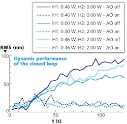
Using the PCDM, actuator arrays of from 2 × 2 to 8 × 8 in size were tested. The results allowed the researchers to select a 5 × 5 array for the actual deformable mirror to be used in the HiLASE laser (see figure). The researchers note that their setup can also be used as a test bench for AO systems to be used in other multi-slab lasers.
REFERENCE
1. Jan Pilar et al., Appl. Opt., 53, 15, p. 3255, May 20, 2014.

John Wallace | Senior Technical Editor (1998-2022)
John Wallace was with Laser Focus World for nearly 25 years, retiring in late June 2022. He obtained a bachelor's degree in mechanical engineering and physics at Rutgers University and a master's in optical engineering at the University of Rochester. Before becoming an editor, John worked as an engineer at RCA, Exxon, Eastman Kodak, and GCA Corporation.
