Mechanical Scanners: Risley prism scanners improve on gimbal/galvo alternatives

For applications such as standoff remote sensing and spectroscopy, coupling a scanning device to the laser-based test instrumentation allows the user to obtain a spatial-detection map that can be more comprehensive than a point-based data-sampling approach. Because traditional carried-axis gimbal scanners can be heavy and subsequently require more driving energy while non-carried-axis galvanometers have limited aperture sizes, Risley-prism-based scanners such as those from Optra (Topsfield, MA) can offer a lighter, more compact, vibration-insensitive scanning option.
A Risley prism pair consists of two prisms with the same physical angle that, when operated in series and rotated about a common optical axis, deflect an optical beam passing through the pair. Minimum deflection occurs when the two prisms are in opposition; maximum deflection occurs when the prism apexes are aligned; and intermediate deflections are achieved by rotating the prisms with respect to each other.
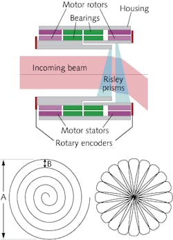
Rotating a pair of Risley prisms with their locations fixed relative to each other traces out a circle with a maximum cone angle of deflection defined by the prism material and wedge angle. Prisms can be made of a single material for single-wavelength operation, or can be achromatic to accommodate broader spectral ranges. Currently, Optra scanners incorporate prisms that can produce clear apertures up to 200 mm for cone angles up to 120° (compared to 75 mm and 80°, respectively, for conventional galvanometer-scanner designs).
Risley prism scanner design
For the Optra scanner, which uses commercial-off-the-shelf (COTS) components, a Risley prism pair is actuated using hollow-core rotary motors with duplex bearings linked to rotary angle optical feedback encoders (see figure). Digital signal processing and closed-loop motion control convert angular pointing commands to prism-rotation angles in order to point the beam along a specified direction or create a spiral, rosette, or other scan pattern by setting the prism rotation velocities to a constant value.
The Risley prism scanner has a low moment of inertia that reduces power consumption, has no cantilevered elements, and is insensitive to vibration. The scanner operates over ultraviolet to long-wave infrared wavelength ranges and has a peak scan speed of 6000 rpm with ≥75 Hz closed-loop bandwidth and ≤175 ms full-field slew time, all for the specified maximum 120° cone angle at resolutions and repeatabilities of ≥100 μrad with accuracy ≤1 mrad.
Motion control is user-defined in either a constant or step-stare steering or scanning mode. Popular configurations for step scan or high-speed scan operation with 25 or 50 mm clear aperture have peak response times from 175 to 350 ms for 500–6000 rpm speeds, weigh <3 kg, and consume <30 W of power.
“Perhaps forgotten or overlooked as a mid-19th century technology, Risley prism systems have a unique combination of scanning field, modest aperture, and size that deserve a new look for next-generation scanning systems,” says Craig Schwarze, principal systems engineer at Optra. “We believe the technology will have high value for applications requiring compact beam steering, whether it be looking for trace explosives from a safe standoff, performing reconnaissance from an unmanned aerial vehicle, or performing free-space optical communications between moving platforms.”
About the Author

Gail Overton
Senior Editor (2004-2020)
Gail has more than 30 years of engineering, marketing, product management, and editorial experience in the photonics and optical communications industry. Before joining the staff at Laser Focus World in 2004, she held many product management and product marketing roles in the fiber-optics industry, most notably at Hughes (El Segundo, CA), GTE Labs (Waltham, MA), Corning (Corning, NY), Photon Kinetics (Beaverton, OR), and Newport Corporation (Irvine, CA). During her marketing career, Gail published articles in WDM Solutions and Sensors magazine and traveled internationally to conduct product and sales training. Gail received her BS degree in physics, with an emphasis in optics, from San Diego State University in San Diego, CA in May 1986.