Chirped Bragg gratings compensate for dispersion
Bragg gratings provide dispersion compensation for 1550-nm telecommunications networks without introducing nonlinear effects, allowing increased data rates.
There is escalating pressure on global telecommunications networks to provide higher transmission capacity, achievable by increasing data transmission rates from 2.5 to 10 Gbit/s. The single biggest issue in the deployment of systems operating at 10 Gbit/s is dispersion, which can introduce errors in the data stream if left unchecked. Fiber Bragg gratings offer a flexible, economical solution to this problem.
Most of the long-haul telecommunications traffic today is carried on synchronous optical networks operating at 2.5 Gbit/s. Last year, companies such as Ciena (Linthicum, MD) and Lucent Technologies (Murray Hill, NJ) used dense-wavelength-division-multiplexing (DWDM) techniques to demonstrate 40-Gbit/s capability by transmitting data across 16 channels at rates of 2.5 Gbit/s. The component requirements for full utilization of such systems are difficult to meet in practice. Coupled with the limited bandwidth and the nonuniformity of erbium-doped fiber-amplifier (EDFA) gain, DWDM at 2.5 Gbit/s may have reached a practical limit with 16 channels.
Transmission capacity also can be increased by raising the rate to 10 Gbit/s. At this data rate, a DWDM system can reach 40 Gbit/s with only four channels. Although this sounds attractive from a systems point of view, successful deployment of such systems will depend on resolving a number of critical issues, foremost among them chromatic dispersion.
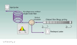
Chromatic dispersion in lightwave systems is caused by a variation in the grou¥velocity in a fiber with changes in optical frequency. A data pulse usually contains a spectrum of wavelengths introduced by modulation. As the pulse travels along the fiber, the shorter-wavelength components travel faster than the longer-wavelength components (see Fig. 1). This effect broadens the pulse to the point that it eventually interferes with neighboring pulses to introduce errors in the data.
A large proportion of the worldwide installed fiber base consists of conventional fiber that is optimized for near-zero dispersion in the second transmission window of 1310 nm. Current transmission systems operate in the third transmission window of 1550 nm, however, to take advantage of low-loss transmission and the availability of EDFAs. For transmission at 1550 nm, conventional fiber introduces high levels of chromatic dispersion--approximately 17 ps/nm/km. Erbium-doped fiber amplifiers are inherently analog devices, so the chromatic dispersion accumulates, becoming the primary limiting factor to capacity.
Dispersion compensation
Chromatic dispersion thus places a practical limit on the distance a signal can be transmitted before some form of compensation becomes necessary. At rates of 10 Gbit/s this distance is about 60 km, and at higher data rates the distance shortens. A number of solutions have been proposed for this problem, including dispersion-compensating fiber (DCF), chirped fiber gratings, mid-span spectral inversion, multilevel coding, and others. Although some of these techniques are of interest from a research point of view, only dispersion-compensating fiber and chirped fiber gratings have been considered seriously as potential candidates for practical deployment.
Conceptually, the simplest way to compensate for the total accumulated dispersion in a fiber link is to concatenate standard fiber with a fiber introducing high levels of dispersion of the opposite sign. Typically, DCF is five to ten times as dispersive as conventional fiber. To compensate for dispersion introduced by an 80-km span, a system requires about 16 km of DCF. To package this length of fiber while maintaining good bending performance results in a bulky, impractical package.
This type of fiber also suffers from higher attenuation than conventional fiber. Over the long lengths required, the fiber introduces significant losses, typically 5 to 8 dB over an 80-km span. This must be compensated for by use of additional amplifiers, increasing system cost.
To achieve high dispersion in DCF, the core diameter is usually small--about 4 µm, compared to 9 µm for conventional fiber. Fiber nonlinear effects are inversely proportional to the effective modal area, so the reduced core diameter increases DCF-induced nonlinearities by a factor of two to four. These nonlinearities have become the ultimate limitation to the use of this technology at high data rates.
Dispersion compensation with gratings
Over the last couple of years, chirped fiber gratings have emerged as the most promising solution for dispersion compensation. Although the idea of using a chirped Bragg grating was proposed as early as 1987, the fabrication of gratings capable of compensating a realistic amount of dispersion with practical bandwidths required the availability of long (10 cm) phase masks.1 Since that time, the viability of using long chirped gratings as dispersion compensators has been demonstrated in field trials with 10-Gbit/s systems.
Dispersion-compensating gratings are based on fiber-Bragg-grating technology. To generate a fiber grating, the refractive index of the fiber is periodically modulated by illumination with ultraviolet light patterned by a phase mask (see Laser Focus World, Nov. 1996, p. S5). Light propagating through the fiber grating with a wavelength twice that of the grating period undergoes reflection. This period-matching is known as the Bragg condition--hence the name Bragg grating.
For a dispersion-compensating grating, the grating period is chirped, or linearly reduced in period along the length of the fiber (see Fig. 2). The grating achieves the Bragg condition (reflection) for shorter wavelengths at a point further into the device than for longer wavelengths. The device thus imposes a delay on shorter wavelengths relative to longer wavelengths, correcting the chromatic dispersion introduced by the transmission fiber.
The gratings act as highly dispersive filters--a 10-cm-long grating can compensate for the dispersion introduced by 80 km of standard fiber over a practical bandwidth of 0.5 nm. Longer distances can be compensated with a narrower bandwidths. In practical systems, however, transmitter wavelength drift caused by temperature fluctuations and device aging necessitates a broader bandwidth.
Fiber gratings are reflective devices so an optical circulator must be used to separate the input of the device from the output. In the past, the relatively high cost of circulators was an issue in the practical application of dispersion-compensation gratings. As the price of circulators drops, however, this is no longer considered a major issue.
Practical gratings
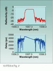
Chirped gratings are now commercially available from companies such as Bragg Photonics (Dorval, Que., Canada), with DCG-40 compensating 40 km of standard fiber with a bandwidth of 1 nm, and DCG-80 compensating 80 km of standard fiber with a bandwidth of 0.5 nm. Single-channel devices are available that operate at the standard wavelengths established for DWDM systems (see Fig. 3). Each device provides dispersion compensation for a specific channel. A four-channel system would thus require four gratings, one for each wavelength, but multiple gratings can be mounted on a single standard rack.
The narrow bandwidth of dispersion-compensating gratings requires that they be contained in a temperature-stable package to operate over the normal temperature range for telecommunications systems. There are various approaches to such packaging, and the technology for this is quite mature.
Dispersion-compensating gratings do not suffer from the disadvantages of the fiber approach. They are compact, low loss, and polarization-insensitive. In addition, they do not have high optical nonlinearity that has become the primary drawback of DCF.
As telecommunications networks go to higher bit rates, these gratings have an added advantage. Simulations show that system tolerance to dispersion decreases from 450 to 60 pS as the bit rate rises from 10 to 40 Gbit/s.2 The fiber-dispersion curve in the EDFA spectral window has a slope, so each DWDM channel experiences slightly different dispersion. The OC-768 protocol for 40-Gbit/s data transmission requires a 60-ps delay between pulses, requiring dispersion compensation to be individually set for each channel. Channel-specific dispersion compensation can be accomplished quite easily with dispersion-compensating gratings but is not possible with DCF.
Dispersion compensation is a major issue for telecommunications networks operating at data rates in excess of 2.5 Gbit/s. Dispersion-compensating fiber has merits, but it is rapidly becoming clear that the high nonlinearities associated with DCF, together with the high losses and bulky packaging, make it impractical. Recent advancements in Bragg-grating technology, however, have shown the viability of using such gratings for dispersion compensation at 10 Gbit/s, along with the ability to provide a solution at higher data rates. o
REFERENCES
1. R. I. Laming, OFC `96 Tech. Digest, paper #ThA5, (1996).
2. K. Ogawa, OECC `97 Tech. Digest, 8A1-1, 8, (1997).
FIGURE 1. Chromatic-dispersion effects introduced by fiber cause spectral spreading in data pulses. If the pulses spread far enough, they begin to overla¥one another, generating errors in the data stream.
FIGURE 2. In chirped Bragg gratings, the grating period is reduced linearly along the length of the fiber. The grating achieves the Bragg condition (reflection) for shorter wavelengths at a point further into the device than for longer wavelengths. By imposing a delay on shorter wavelengths relative to longer wavelengths, the grating corrects for the chromatic dispersion introduced by the transmission fiber.
FIGURE 3. Commercially available, single-channel dispersion-compensation grating designed to compensate for 80-km link offers good reflectivity across the channel bandwidth (top) with small group-delay characteristics (bottom).


