OLIVER DROSS, RUBÉN MOHEDANO, MAIKEL HERNÁNDEZ, ALEKSANDRA CVETKOVIC, PABLO BENÍTEZ, and JUAN CARLOS MIÑANO
Abbe and Köhler illumination are standard methods used to provide uniform illumination on a target.1, 2Abbe illumination works well only if the source itself has uniform irradiance. Typical sources like incandescent filaments, discharge lamps, and light-emitting diodes (LEDs) do not meet this criterion.
In Köhler illumination, each point at the target area is illuminated by the entire source so that irradiance variations across the source do not affect the target illumination. However, if a single element (mirror, lens) is used to collect the flux of the source, intensity variations of the source limit the achievable uniformity. If small refractive or reflective facets are used instead, each facet receives almost constant irradiance so that arrays of such facets can provide high uniformity and efficiency at the same time. These lenticular (faceted) Köhler integrators can be applied for light homogenization but also to create special features such as sharp cut-offs or gradients in the output pattern.
Integration in one direction
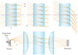
Consider two symmetrical lenslet arrays on both sides of a dielectric element of thickness t, where this thickness is equal to the focal length f of each lenslet (see Fig. 1). If no aberrations are present, all light hitting one lenslet array with an arbitrary intensity distribution within off-axis angles limited by ±a would be transformed into uniform intensity between ±a after the second lenslet, as long as the irradiance of the incoming light is constant over each lenslet. This condition can be met by choosing the lenslets sufficiently small. The output intensity of the integrator, or the irradiance if a collimation system is used downstream, will be a sharp flat-top distribution that does not depend on the source irradiance (any “structure” of the source is lost).
If the integration zone is larger than the source, the source can be moved within the integration zone without affecting system performance, which will help relax the placing tolerances of the optical components.
The angular acceptance of integrators is limited by the image formation quality of the lenslets. For low f numbers, the image formation between the lenslet arrays deteriorates, so that the resulting integrated pattern becomes fuzzier, less uniform, and less efficient. Light emitted outside of the integration zone is not controlled and may cause artifacts beyond the boundaries of the desired radiation pattern.
By applying rotational symmetry to such microlenses, radial integration can be achieved: While rays in the saggital plane are not integrated, the meridian rays are. The zone of integration becomes a disk but the output depends partially on the source characteristics and the far-field intensity of such a setup is not uniform. The intensity tends to form a peak at or close to the optical axis. The larger the integration diameter and the smaller the width of the source, the poorer the illumination uniformity. However, for some illumination applications the degree of achievable uniformity is sufficient.
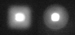
An ultracompact and efficient collimator, a so-called rotational RXI—a generic term for a nonimaging, concentrating optical element—was designed for an LED illumination application that required a very intense hotspot (see Fig. 2).3 In addition, a round secondary light distribution of larger angular spread and much lower intensity was specified by the customer. The part of the RXI that was used to create that secondary light distribution forms an image of the source, so that a square image of the LED chip becomes visible. By adding rotational integration to the lens, this problem was solved.If rotational integration is not sufficient, better uniformity can be achieved with planar microlens arrays. Such devices have been used for decades in microscopy illumination, laser beam shaping, different types of projection, and many other fields. Such systems can be easily designed by using two arrays of rotationally symmetric microlenses. The output replicates the shape of the microlenses such that if high efficiency is a must, the pattern will be rectangular or hexagonal, but not round as frequently specified for illumination purposes.
Integration superimposed on aspheric profiles
Köhler integration is not limited to flat lenslet arrays; it can be embedded onto curved surfaces using a simultaneous multiple surface (SMS) method.4 An example is a lens that has integrating features superimposed onto two aspheric profiles of the original design (see Fig. 3).If the facet is designed to image the center of its corresponding doublet facet (symmetrical design), only in the limit of vanishing aberrations (high f numbers) at S' and T' will the light distribution be sharp. If the facet is designed to image for example the lower edge of its corresponding doublet facet, the light distribution will be perfectly sharp at T' and fuzzy at S' (asymmetrical design). Similar designs are possible for reflector facets or combinations of refractive and reflective facets.
Köhler integration on 3-D surfaces
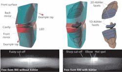
The SMS three-dimensional (3-D) designs can, when two freeform surfaces are designed, ensure almost perfect imaging of the boundaries of an extended source onto a target.5, 6 A freeform RXI can be designed as a single dielectric solid in which light emitted by an LED undergoes a refraction at the input cavity surface, followed by a total internal reflection on the inside of the front surface, a reflection on the back mirror, and finally a refraction on the front surface, which therefore acts twice on the light (see Fig. 4). The RXI can be designed to be a very efficient collimator that can create radiation patterns of different vertical and horizontal spread as needed for automotive low-beam lights, for example.7The low-beam light distribution is defined by very demanding legal photometric test specifications like a horizontal cut-off line (or gradient) at which the intensity must drop from the hotspot of 20 to 50 kcd to almost 0 within one to two vertical degrees. Such a cut-off can be achieved by imaging the edge of a light source, such as an LED, to the horizon. Then, however, the light distribution depends on the LED edge “sharpness,” the LED positioning tolerance, and may replicate many undesired features of the LED. Adding integrating functions to the freeform design can solve these problems. In three dimensions the microlens edge points become curves in space. Two types of Köhler integration concepts are possible: the integration is provided for just one direction (the up-down direction), or integration in two directions at the same time (up-down and left-right).
In the first step, two freeform surfaces (either refractive or reflective) are calculated by the 3-D SMS method. These freeform surfaces only serve as the basis on which to construct the microlenses.8 The front surface is kept unchanged, while the cavity that allocates the LED and the back mirror is split in equal numbers of facets that perform the Köhler integration. To sharpen the cut-off, these facets are designed in such a way that the optic images the sharp ridges of microlenses on the cavity onto the far field cut-off line. In this case, the design contains six Köhler facets that integrate only in one direction and a total of 12 (2 × 6) facets integrating in two directions.
Köhler integrating optics consisting of two arrays of lenticular elements can improve the performance of nonimaging optical designs considerably—unwanted source features can be eliminated and the output uniformity dramatically improved. If integration in one direction is applied, all light in the outgoing radiation pattern can be confined between two sharp boundaries or a single sharp gradient can be created (symmetrical or asymmetrical integration, respectively). Two-directional integration can confine the light within rectangular boundaries to create perfectly uniform output, or create two perpendicular or angled sharp edges in the light pattern. All designs can be superimposed onto flat or spherical reflective and refractive surfaces as well as sophisticated freeform optics, so that no additional optical elements are being added. The basic optical behavior of the underlying optical design is maintained. Disadvantages like more complex tooling, slight losses of efficiency, or a certain ètendue dilution are offset by partially decoupling the light output from the light source position and irradiance characteristics.9
REFERENCES
- M. Born and E. Wolf, Principles of Optics, Pergamon, Oxford (1975).
- W. Cassarly, Handbook of Optics, 2nd ed., p. 2.23, McGraw-Hill, New York (2001).
- R. Winston, J.C. Miñano, and P. Benítez, “Nonimaging Optics”, Elsevier-Academic Press, New York, (2005).
- J.C. Miñano et al., Applied Optics 34(34) p. 7850 (1995).
- P. Benítez et al., Optical Engin. 43(7) p. 1489 (2004).
- P. Benítez et al., Patent “Three-Dimensional Simultaneous Multiple-Surface Method and Free-form Illumination-Optics Designed Therefrom,” U.S. Utility Application 10/901,919.
- O. Cross et al., Proc. Int’l. Symposium on Automotive Lighting ISAL (2005).
- J.C. Miñano et al., “Nonimaging Optics and Effic. Illumin. Sys. II,” SPIE Proc., R. Winston & T.J. Koshel ed. (2005).
- O. Dross et al., Proc. SPIE 7103, 71030G (2008); DOI:10.1117/12.798111.
Oliver Dross is technology director and Rubén Mohedano and Maikel Hernández are optical scientists at Light Prescriptions Innovators (LPI) Europe, CeDint, Campus Montegancedo, 28223 Madrid, Spain; e-mail: [email protected]; www.lpi-llc.com. Aleksandra Cvetkovic is a Ph.D. student, Pablo Benítez is a professor, and Juan Carlos Miñano is chair professor at Universidad Politécnica de Madrid, Cedint, Campus Montegancedo, 28223 Madrid, Spain. Pablo Benítez and Juan Carlos Miñano are also associates at LPI, 2400 Lincoln Ave., Altadena, CA 91001.


