Lens-mounting method is drop-in simple, yet machine-centering accurate

Combining the simplicity of the drop-in method (where machining tolerance of the lens mount is tight enough that lenses can be dropped into their housing without adjustment) with the centering precision and accuracy of machine-assisted alignment, a new auto-centering lens-mounting method from the National Optics Institute of Canada (INO; Quebec City, QC, Canada) uses the geometrical relationship between the lens diameter, radius of curvature, the thread angle, and the thread profile of the retaining ring.
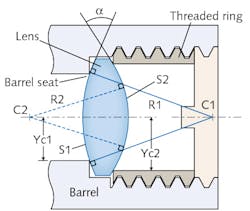
With C1 and C2 as the center of curvature of the first and second surface, respectively, with radius of curvature R1 and R2 and Yc1,Yc2 being the half-diameter between the lens optical axis and its seat, the lens-mounting method enables lens centering typically to less than 5 μm (or < 0.25 arcmin) for all lens geometries with a clamping angle larger than 14°. The patent-pending technique does not require manual alignment or tight manufacturing tolerances; in fact, it actually relaxes lens and barrel bore diameter tolerances along with lens wedge tolerances.
To implement the method, lens barrels should be designed such that Δtilt (mm) = Δring (mm), where Δtilt is the lateral decentering of the center of curvature of the lens surface in contact with the retaining ring resulting from the tilted retaining ring and Δring is the lateral decentering of the center of curvature of the lens surface in contact with the retaining ring resulting from the retaining ring decenter. With an auto-centering condition defined as:Once the thread angles and profiles of the barrel and ring are machined according to the prescription (and provided that the lens is free to move as imposed by the motion of the retaining ring), any decentering of the ring, and thus of the lens, is precisely compensated by a tilt of the ring that in turn pushes the lens so as to keep it centered on the barrel axis. Reference: INO Auto-centering Technology Technical Note on Criterion of Centrability, INO-090201_1-0007 (2015).
About the Author

Gail Overton
Senior Editor (2004-2020)
Gail has more than 30 years of engineering, marketing, product management, and editorial experience in the photonics and optical communications industry. Before joining the staff at Laser Focus World in 2004, she held many product management and product marketing roles in the fiber-optics industry, most notably at Hughes (El Segundo, CA), GTE Labs (Waltham, MA), Corning (Corning, NY), Photon Kinetics (Beaverton, OR), and Newport Corporation (Irvine, CA). During her marketing career, Gail published articles in WDM Solutions and Sensors magazine and traveled internationally to conduct product and sales training. Gail received her BS degree in physics, with an emphasis in optics, from San Diego State University in San Diego, CA in May 1986.

