Novel Optics: Advances in MRF enable better mid-spatial frequency correction on precision optics
CHRIS MALONEY
The optics industry is advancing towards tight form, figure, mid-spatial frequency (MSF), and roughness specifications for all part geometries: planos, spheres, aspheres, and even freeforms. Historically, magnetorheological finishing (MRF) has been implemented successfully to produce such high-margin optics. Certain applications, such as high-energy laser, lithography, and x-ray, require even tighter MSF and roughness specifications than ever before. MRF technology has adapted to meet the needs of these applications. Advancements in MRF technology have enabled the ability to correct MSF errors as small as ~1 mm and also improve surface roughness on many materials to ~1 Å root-mean-squared (RMS).
Manufacturing of a high-precision freeform optic using MRF
To illustrate the advancements that have been made in MRF and for the sake of discussion, let us focus on an example where the customer has requested an off-axis, parabola-like mild freeform optic. As an aside, most of what will be discussed here can also be applied to planos, spheres, and aspheres, as well as "perfectly bad" compensating surfaces.
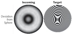
In this case, the freeform optic has a diameter of ~150 mm and a best-fit concave radius of ~200 mm. To produce the freeform optic, our most efficient route will be to start with an off-the-shelf sphere of the same diameter with the best-fit radius. Figure 1 shows measured fringes of the incoming optic as well as the fringes of the target freeform shape that will be induced into the sphere. Approximately 12 waves (λ) peak-to-valley (PV) of freeform shape will be introduced into the surface of the sphere.
Optimal MRF process flow
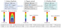
To produce this freeform optic from the starting sphere, there are four spatial-frequency "regimes" that should be considered. The first is the global form of the part. To induce the freeform shape with MRF, the largest tool size (150 mm wheel) with the most aggressive fluid (D11 fluid) and settings should be used to keep cycle time down. The second regime is the figure error of the part. Any low-order errors that remain after the freeform introduction can be corrected with a smaller tool size (50 mm wheel).
The third band that we care about contains the MSFs. To address this, the smallest tool size (20 mm wheel) paired with C30 fluid (which is QED's newest, lowest roughness, and lowest removal rate fluid) can be used to target errors that are as small as ~1 mm. The small tool size is chosen to increase the correction efficiency of the removal function for higher frequencies. In addition, C30 fluid is chosen for its low removal rate property. A lower removal rate fluid can help the computer numerical control (CNC) platform that MRF is built around correct MSF errors by allowing the machine to accelerate and decelerate more slowly than it would when using more-aggressive fluids. By constraining the machine less, less uniform removal is required to make the targeted correction, which results in less unpredicted removal errors.
Finally, the fourth spatial frequency regime, surface roughness, can be improved "for free," depending on the material being polished and the MRF fluid that is chosen. Since the final MRF step shown here is using C30, the lowest roughness fluid, we can expect a final surface roughness of ~1–2 Å RMS on a wide range of materials, including BK-7, fused silica, calcium fluoride, and silicon. Figure 2 depicts the three MRF steps required for an efficient freeform shape introduction into the surface of the sphere. The relative size of the removal function that is to be used for each step is illustrated.After reviewing this process, one thing that an experienced MRF user might ask is, "How can it be efficient to change wheels or fluid between each polishing run?" On legacy MRF platforms, a wheel change could take on the order of two or three hours and a fluid change could take about half of a day for experienced users. One improvement that has been made to the current Q-flex MRF platform is that it has been designed to be modular to accommodate fast and easy wheel and fluid changes (~15 minutes). This enables optics manufacturers to design progressive MRF processes that work towards smaller tool sizes and lower roughness/less aggressive fluids. This concept is what makes the fine-finishing step using the 20 mm wheel and C30 fluid a feasible option to correct MSF errors as well as improve surface roughness.
Should I use raster or rotational mode?
For the most-efficient MSF improvement, we now know that we should use the smallest tool size possible and the lowest removal rate (C30) fluid, but what about the polishing mode? Given a choice between raster or rotational polishing, which will result in better MSF corrections?
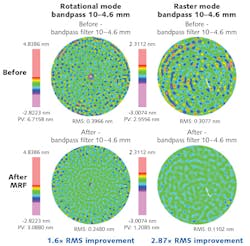
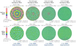
To better understand this dilemma, we ran a test where we started with two optics of the same prescription with similar incoming errors and subjected each optic to our fine-finishing process, one in rotational mode and the other in raster mode. Figure 3 shows the results of this test while only looking at the spatial period band between 10 and 4.6 mm. It is clear that the raster-mode fine-finishing step improved MSF errors more efficiently than rotational mode.For the rotational mode polishing result, it is noticeable that the correction near the middle of the part is more efficient than the correction near the edge of the part. This is mostly because of the nature of the rotational solving algorithm. This solve is calculated in polar coordinate space, where additional "orders" are added as the solve progresses—meaning that the error is fit by more and more cycles per revolution. As a result of this behavior, each degree near the center of the part captures higher lateral frequency errors than each degree near the edge of the part.
For raster polishing, the solve algorithm is handled in Cartesian coordinate space, resulting in a uniform solve for MSF errors across the entire part. In addition, raster polishing can be used to completely avoid leaving a center artifact in the part.
The Q-flex platform has been designed to enable raster polishing of spheres, aspheres, and wild freeform shapes. Legacy MRF platforms could only support raster polishing over a limited range of geometries. For the most-efficient MSF correction, the fine-finishing step should make use of the 20 mm wheel, C30 fluid, and freeform raster-mode polishing.
Implementation of fine figure correction
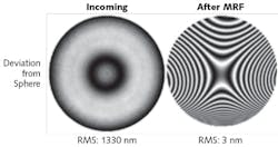
By following the MRF process flow as depicted in Fig. 2, it was possible to start with an RMS error from the desired freeform shape of ~12 λ PV and improve the surface to λ/30 PV in just three polishing runs and with a total polishing time of 6 hours. Figure 4 shows the actual fringes that were measured showing the deviation from the initial sphere prescription. The "After MRF" image is almost identical to the "Target" image in Fig. 1. In this case, each polishing run was completed using raster-mode polishing to avoid any center artifact and also for the most-efficient MSF correction.The latest MRF platform enables fast head changes and fluid changes, allowing for progressive MRF processes that work toward smaller tool sizes and lower-roughness/less-aggressive fluids. This allows the operator to quickly switch to the fine finishing process using the 20 mm wheel and C30 fluid. In addition, new freeform raster-mode polishing capabilities are available that support spheres and aspheres with a half angle up to 45°. The combination of raster-mode polishing with the 20 mm wheel and C30 fluid can be used as a true final finishing step to target nanometer-level amplitude errors, improve MSF errors with a wavelength as small as ~1 mm, and achieve ultralow roughness.
Chris Maloney is an applications engineer at QED Technologies, Rochester, NY; e-mail: [email protected]; https://qedmrf.com.
