ASTRONOMICAL IMAGING: 3D spectrophotometric imaging opens a new window into the cosmos
JOSS BLAND-HAWTHORN and JEREMY ALLINGTON-SMITH
Over the past 20 years, astronomers have made huge strides in extracting very detailed information from two-dimensional (2D) cosmic images. The public is accustomed to seeing astonishing images from the Hubble Space Telescope of distant nebulae. Such images provide scientists with important clues, but there is far more to be learned if the light from each pixel is dispersed along a third axis—the spectral dimension. If this can be done efficiently for all pixels in the image, the result is a three-dimensional (3D) data cube rather than a simple 2D image; that is, a stack of narrowband 2D images where common pixels in each image make up a spectrum.
Each spectrum often shows evidence of emission or absorption lines that betray the presence of chemical elements. We can compare the relative strengths of these lines to learn about the chemistry and physical conditions within the source. If the lines are redshifted or blueshifted, we can learn how different parts of the object are moving with respect to each other. Spectral information is so incredibly informative that it accounts for the lion's share of astronomical observations today.
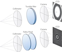
So how do astronomers convert a 2D imaging system into a 3D system? There are two basic methods: tunable filters and integral field spectrographs, although both of these have many variants. For tunable filters, a rich variety of physical phenomena can isolate a finite spectral band: absorption, scattering, diffraction, evanescence, birefringence, acousto-optics, single-layer and multilayer interference, multipath interferometry, and polarizability among many others.1 The different techniques rely ultimately on the interference of beams that traverse different optical paths to form a signal. Integral field spectrographs involve redirecting light with microlens arrays or with image slicers, although there are new directions under investigation.
Tunable filters
While tunable filters are a relatively recent development in nighttime astronomy, they have long been used in other physical sciences such as solar physics, remote sensing, and underwater communications. With their ability to tune precisely to a given wavelength using a bandpass optimized for the experiment, tunable filters are already producing some of the deepest narrowband images to date of astrophysical sources. The ideal filter is an imaging device that can isolate an arbitrary spectral band, Δλ, at an arbitrary wavelength, λ, over a broad, continuous spectral range—preferably with a response function that is identical in form at all wavelengths. The final 3D "data cube" is essentially the stack of images that results from observations over a sequence of consecutive wavebands.
The technologies that come closest to the ideal tunable filter are the airgap Fabry-Perot and the Fourier-transform interferometer. To understand why, we highlight the Taurus Tunable Filter (TTF), which was the first general-purpose device for nighttime astronomy.2 Interference is formed between two highly reflective, moving plates (see Fig. 1). To be a useful filter, not only must the plates move through a large physical range but they must start at separations of only a few wavelengths.
For an order of interference m, the resolving power, R, is approximately mN, where N is the instrumental finesse. The condition for photons with wavelength λ to pass through the filter is mλ = 2lcos θ where l is the airgap spacing and θ is the angle of the ray to the optical axis. The finesse is determined by the coating reflectivity and, in an ideal system, the number of recombining beams. For the TTF, the plates can be scanned over the range l = 1.5-15 μm, and the orders of interference span the range m = 4–40, such that the available resolving powers are approximately 100–1000.
The sharp core of tunable-filter transmission profiles is not ideal. Even a small amount of flatness at peak transmission will avoid narrowly missing most of the spectral line signal from a source. In theory, all band-limited functions can be squared off, but in practice this is difficult to do. Since the Michelson interferometer (filter) obtains its data in the frequency domain, the profile can be partially squared off at the data-reduction stage through a suitable choice of convolving functions.
An alternative technology is the acousto-optic tunable filter (AOTF). This electronically tunable filter makes use of acousto-optic (either collinear, or more usefully, noncollinear) diffraction in an optically anisotropic medium. These AOTFs are formed by bonding piezoelectric transducers such as lithium niobate to an anisotropic birefringent medium. The medium has traditionally been a crystal, but polymers have been developed recently with variable and controllable birefringence. When the transducers are excited to 10-250 MHz (radio) frequencies, the ultrasonic waves vibrate the crystal lattice to form a moving phase pattern that acts as a diffraction grating. The diffraction angle (and therefore wavelength) can be tuned by changing the radio frequency.
Integral field spectrographs
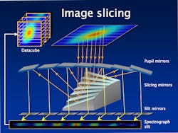
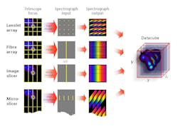
A 3D spectrograph divides up the source image in the focal plane using either slicing mirrors, lenslet arrays, optical fibers, or a microlens/micromirror hybrid system. The required reformatting of the field is done by an integral field unit (IFU). The image slicer for NASA's SNAP satellite mission illustrates the main features of this technology (see Fig. 2).3 The image is divided by N mirrors into long thin slices, angled so that each slice traverses a different optical path before they are reassembled end-to-end to form the entrance slit of the spectrometer. The light through the slit is dispersed by the spectrometer into a full spectrum of all parts of the original 2D field without losing data due to overlaps. Invented at the Max Planck Institute in Munich, it was optimized by Durham University by adding curvature to the optical elements to reduce the size of the instrument.4,5 This technique is used for the IFU of the James Webb Space Telescope and for the multiobject spectrograph being completed for the Very Large Telescopes of the European Southern Observatory in Chile.Fiber arrays were originally exploited due to their simplicity. To boost efficiency, these are generally used with a lenslet array to focus the light into an array of spots that is captured by a matching array of fibers. The fiber-to-fiber spacing can be much larger than the core diameter because the lenslets focus all the incoming light into the fibers and provide optimum impedance matching. Most importantly, the fibers reformat the 2D field into a 1D slit to make optimal use of the detector area without compromising the length of the spectrum.
In recent years, this image slicer has become the preferred choice of dicing up the telescope focal plane,6 a technology than can trace its roots back to Bowen (1938).7 The use of differentially tilted mirrors gives the designer some freedom to optimize the coupling of the telescope and spectrograph leading to an efficient system with minimal dead space at the detector. Fore-optics are required that anamorphically magnify in the dispersion direction roughly twice as much as in the slit/slice direction to allow optimal sampling in both spatial dimension and wavelength simultaneously. This boosts efficiency in the infrared by squeezing the beam in the spectral direction to reduce losses due to diffraction at the slit.
The microslicer technique is a hybrid of the lenslet and image slicer techniques that is well suited to large fields where other techniques are too complex and bulky—especially if the spectral coverage does not need to be large. It has the advantage of reducing the size of instruments on the next generation of extremely large telescopes. It uses a microlens array to divide the field in 2D to feed a set of microslicing mirrors. This approach exploits the anamorphic properties of crossed-cylindrical arrays to allow each pupil image to be replaced by a slice that contains spatial information along its length.
What we have learned
Three-dimensional imaging has been crucial to understanding the workings of active and starburst galaxies. It is now known that all galaxies, including our own, have a supermassive black hole at their centers that periodically flares up, disrupting the formation of stars and therefore regulating the evolution of galaxies on cosmic timescales. The furthest detectable galaxies provide clues as to when stars and galaxies first formed. Spectral imaging has revealed their structure, internal motions, and hence their probable mass, helping to fit them into an evolutionary story.
Nearer to home, spectral imaging plays a vital role in the study of stars at the start and end of their lives and in identifying debris in stellar systems that might later be hosts to Earth-like planets. Even closer to home, these benefits are not restricted to astronomy but are being explored for biomedical science, energy research, and Earth observation. Examples include in vivo spectral mapping of short-lived spectrally tagged cell cultures and Tokamak plasma diagnostics.
Future concepts
Future 3D spectrographs make more extensive use of telecommunications and astrophotonic developments, allowing them to tackle the problem of reformatting the patchy information content of the telescope focal plane; that is, the sky is not uniformly filled with celestial sources. Possible technologies may include digital micromirror devices where light can be directed in different directions over a p × p pixel format. Two such devices used in series can reformat an arbitrary input to a fixed output spectrograph, much like in telecom switching. Another interesting development is the growth in 3D photonic devices by injecting ultrafast laser pulses directly into a substrate. Compact networks of microspectrographs imprinted onto stacked optical circuit boards are already upon us.8
REFERENCES
1. J. Bland-Hawthorn and P. Murdin, Tunable Imaging Filters, Encyclopedia of Astronomy and Astrophysics, http://eaa.crcpress.com/default.asp?action=summary&articleId=5401 (2001).
2. http://www.aao.gov.au/ttf
3. A. Ealet, "An image slicer spectrograph for the SNAP mission," SPIE Newsroom, http://spie.org/x19169.xml?ArticleID=x19169 (Jan. 20, 2008).
4. L. Weitzel et al., "3D: The next generation near-infrared imaging spectrometer," Astronomy and Astrophysics Supplement Series, 119, 531-546 (1996).
5. R. Content, Astrophysical Journal, 464, 412 (1996).
6. J. Allington-Smith, "Basic principles of integral field spectroscopy," New Astronomy Review, 50, 244-251 (2006).
7. I.S Bowen, "The Image Slicer: A Device for Reducing the Loss of Light at the Slit of a Stellar Spectrograph," Astrophysical Journal, 88, 113 (1938).
8. J. Bland-Hawthorn et al., "PIMMS: photonic integrated multimode microspectrograph," SPIE Conference Series, 7735 (2010).
Joss Bland-Hawthorn is a Federation Fellow at the University of Sydney, School of Physics A28, NSW 2006, Australia, and a Leverhulme Professor at the University of Oxford; e-mail: [email protected]; www.physics.usyd.edu.au. Jeremy Allington-Smith is a reader at Durham University and associate director of the Centre for Advanced Instrumentation, Physics Dept., Rochester Building, South Rd., Durham DH1 3LE, England; e-mail: [email protected]; www.durham.ac.uk.


