FLUORESCENCE IMAGING: Optical filters optimize laser-based fluorescence imaging systems
Because of their high brightness, stability, longevity, and narrow spectral bandwidth, lasers have been advantageously replacing conventional broadband light sources for fluorescence imaging applications. In addition to allowing higher-sensitivity visualization and enhanced throughput in imaging applications, several unique properties of lasers—narrow beam divergence, high degree of spatial and temporal coherence, and well-defined polarization properties—have spawned new fluorescence imaging techniques. However, the advent of lasers as fluorescence light sources imposes new constraints on imaging systems and their components. Optical filters used in laser-based imaging systems, for example, must meet specific unique requirements compared to filters used in broadband-light-source-based instruments.
Going solid-state
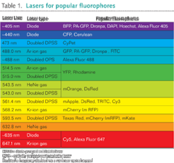
Until recently the most popular lasers for fluorescence imaging were gas lasers with spectral lines at 488, 568, and 647 nm. In the last several years solid-state devices have been replacing gas lasers due to substantially better wall-plug efficiency, smaller size, and lower cost. Popular laser types include semiconductor diode lasers (especially at 405 and 635 nm), optically pumped semiconductor lasers (including a widely used version at 488 nm), and frequency-doubled diode-pumped solid-state (DPSS) lasers (such as the yellow 561 nm laser and the newer 515 and 594 nm lasers; see Table 1).
The narrow spectral bandwidth of a laser effectively excites a fluorophore thereby improving signal, enhancing contrast, and reducing crosstalk in fluorophore-multiplexing assays. Additionally, the ease of maneuverability of inherently low-divergent laser beams has led to the adoption of lasers as the exclusive source of illumination in certain microscopy techniques such as total-internal-reflection fluorescence (TIRF) microscopy. The TIRF method is an epifluorescence technique that enables single-molecule studies via high-sensitivity visualization of cellular dynamics on the plasma membrane of a cell. Similarly, most confocal microscopes utilize laser illumination. A confocal microscope has the advantage of providing enhanced sensitivity of visualization in any focal plane of the specimen, as opposed to TIRF, which is limited to imaging of plasma membrane only.
More recently, the application of lasers in fluorescence has led to a paradigm shift in terms of resolution. Until the development of stimulated-emission-depletion (STED) microscopy, conventional microscopes were limited to a lateral resolution of about 200 nm.1 However, STED, a laser-based technique, has pioneered superresolution microscopy that enhances the resolution of a microscope much beyond the conventional diffraction-limited imaging capability.
Application of lasers, coupled with fluorescent proteins with unique properties of photoactivation, photoswitching, and photoconversion, has enabled many superresolution imaging techniques. For example, photoactivatable localization microscopy (PALM), stochastic optical reconstruction microscopy (STORM), and saturated-pattern-excitation microscopy (SPEM), to name a few, allow visualization of fluorescently labeled samples with tens of nanometers of resolution. These superresolution imaging techniques can accurately localize individual (or a group of) fluorophore molecules. Localization accuracy of a given fluorophore increases dramatically with the number of photons acquired from the given fluorophore and highly efficient optical filters play an increasingly important role in such cutting-edge applications.
The role of optical filters
Different types of optical filters are placed throughout the beam path in a laser-based imaging system (see Fig. 1). For example, three lasers can be combined in a system that allows confocal scanning with both descanned and non-descanned detection paths, each of which has simultaneous multiple-color detection. Alternatively, without the scanning function, this system can be used with a TIRF-compatible objective to perform TIRF imaging.Unlike the traditional soft-coated fluorescence filters used for decades, newer hard-coated thin-film filters made with ion-beam sputtering have high laser-damage thresholds (LDT). High optical durability, combined with the robust environmental reliability of hard-coated filters—virtually impervious to thermal and humidity induced degradation—eliminates the need to ever replace the filters for most fluorescence microscopy applications.
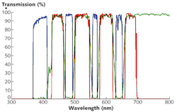
Excitation filters for laser applications also have unique wavelength requirements. Some lasers, like gas lasers and diode-pumped solid-state (DPSS) lasers, have very precise and narrow laser lines. However, selection of a narrow-laser-line clean-up filter is not a good match for systems that might use multiple lasers with similar wavelengths (such as 473 and 488 nm for exciting green fluorescence protein or GFP). Furthermore, the spectral output from diode and optically pumped semiconductor lasers can vary appreciably from laser to laser, with temperature, and as the lasers age. Therefore, for most laser microscopy systems, broader excitation filters that appear similar to those used for broadband-light-source (such as an arc lamp) microscopy systems are a good solution. For example, the ultraviolet (UV) band of a multiband excitation filter can be used with both 375 and 405 nm lasers, with the long-wavelength edge taking into account a ±5 nm uncertainty in the wavelength of the 405 nm laser.
A typical emission filter should provide high blocking (more than OD 6) at all possible laser lines that might be used with the filter set, ensuring the darkest background signal level while providing excellent transmission of the emission signal. It should be noted that not all emission filters for broadband light sources provide sufficient blocking at laser lines and as a result, they can lead to an appreciable compromise in imaging contrast.
Dichroics for laser applications should not only have reflection and transmission bands that are compatible with the excitation and emission filters, but they should also have antireflection coatings to maximize transmission of the emission signal and eliminate coherent interference artifacts. Because the dichroic beamsplitter is directly exposed to the powerful excitation beam, even weak autofluorescence from the filter will contaminate the emission signal. Here, a substrate with ultralow autofluorescence, such as fused silica, is needed.
The dichroic beamsplitter can have a significant impact on the image quality in certain applications, especially if the flatness (or curvature) of the dichroics is not suitable. Even though transmitted wavefront error (TWE) is not significantly affected by substrate curvature, the reflected wavefront error (RWE) can significantly compromise imaging quality. For example, sample illumination may deteriorate in a TIRF microscope when a nonflat dichroic is placed in the excitation light path. To avoid this problem, the dichroic should be flat enough so there is no noticeable shift in the focal spot of the illumination laser beam, where focal shift is typically defined by the Rayleigh range. Similarly, owing to the inherent bending stress introduced by hard coatings, aberrations can be introduced in an imaging beam that is reflected off a dichroic. A sufficient criterion for an imaging beam (focused onto a detector array such as a CCD) reflected off a dichroic is that the diffraction-limited spot size should not change appreciably due to reflection off of the beamsplitter.
New filter demands
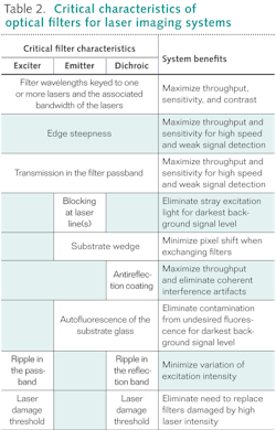
Overall, optical filters should achieve high blocking as well as high transmission of specific wavelengths of light without compromising the diffraction-limited image quality (see Table 2). This simple set of requirements influences the design of an individual filter as well as the system of filters that are used in combination. The designs of the excitation and emission filters as well as that of the dichroic beamsplitter should be complementary to each other to obtain the highest fidelity fluorescence visualization.For laser-based imaging systems, edge steepness of the excitation and emission filters is coupled. High edge steepness significantly affects utilization of the limited bandwidth of light. At the same time, the crossover edge location of the excitation and emission filters should have sufficient blocking (more than OD 6) to make sure that the excitation light does not leak into the emission channel.
Image registration is also affected by the combined performance of the dichroic beamsplitter and the emission filter. It is important to use exceptionally parallel and flat glass substrates to minimize any wedge angles of the substrates (prior to applying thin-film coatings) as well as the curvature of the filters owing to coating stress. Single-substrate filter construction makes it very straightforward to minimize the wedge (several arc seconds for Semrock laser emitters and dichroics) when manufacturing the substrate.
Demanding applications such as imaging of single molecules using TIRF can impose unprecedented constraints on the blocking of laser beams in the emission channel while maximizing the collection of every possible photon from the fluorophores. In such situations, conventional bandpass emission filters can be replaced by a long-wave-pass filter keyed to the specific laser line. In our observation, TIRF systems even benefit from using a second emission filter in conjunction with all the filters of a laser set. The main purpose of the second filter, which should be physically separated from the first emission filter, is to ensure that higher-angle scattered excitation light does not make it through the entire imaging path to the detector.
REFERENCE
- S.W. Hell and J. Wichmann, Optics Lett. 19, p. 780 (1994).

Prashant Prabhat, Ph.D. | Business Line Leader for Semrock Catalog
Prashant Prabhat, Ph.D. is Business Line Leader of Catalog Business at Semrock. Since 2008 he has been an Applications Scientist at Semrock. He earned his Ph.D. in Electrical Engineering from the University of Texas at Dallas and completed graduate research at Ward Lab at the University of Texas Southwestern Medical Center. It was there that he invented multifocal plane microscopy (MUM), a technique that allows for real-time visualization of fast cellular dynamics in 3D. MUM has enabled the discovery of novel trafficking pathways in cells, and formed the basis for 3D super-resolution techniques. At Semrock, he advises researchers on optical filter issues from a systems perspective, and helps develop the company’s product roadmap. As a new venture manager, he also has led the development of a computer controlled tunable filter system.
Turan Erdogan | CTO and Co-Founder, Semrock
Turan Erdogan is CTO and cofounder of Semrock (a unit of IDEX Corporation; Rochester, NY).


