By James Turlo
A simple formula called the Rayleigh equation can be used to define the imaging performance of a lithography system:
Resolution = k1 x wavelength/NA
where NA is numerical aperture, wavelength is the wavelength of light emitted by the gas in the light source, and the k1 factor represents a specific process and the image-resolution enhancement techniques used to improve imaging performance.
The light source affects all three components of this equation. As lens designers increase the NA into the range well above 0.8, the spectral linewidth of the light source must be reduced for optimal imaging and to avoid chromatic aberration. Techniques such as off-axis illumination, phase-shifting, and optical proximity correction reduce the overall effective transmission of the light path, which reduces the throughput of the lithography system. By providing higher light-source power, the throughput can be recovered.
Aside from the operational wavelength of the gas, the two fundamental performance parameters of an excimer light source are power and linewidth. Lithography light sources emit pulses lasting tens of seconds from a single discharge chamber. The resonator consists of a partially reflective mirror on the output side and a line-narrowing module on the backside. The line-narrowing module consists of prisms to spread the light and a reflective grating to tune the wavelength, so line narrowing discards most of the light produced by the discharge chamber.
The implication is that reduced linewidth and increased power are contradicting design requirements on single-chamber excimer light sources. In new light sources, typical linewidths are less than 0.5 pm and power is about 20 to 30 W, a combination near the design limit of single-chamber light sources that still meet numerous, stringent performance requirements as lithography light sources. For ArF light sources, the linewidth requirement will soon fall below 0.25 pm, and the power requirement will exceed 40 W. Single-chamber light sources cannot achieve such a challenging combination for semiconductor manufacturing.
The alternative is to transition to a staged light source using two discharge chambers filled with the same gases. The preferred configuration for lithography includes a master oscillator (MO), whose purpose is to produce extremely narrow linewidth. Higher-dispersion prisms can be used to narrow the spectrum at the expense of discarded pulse energy. The second chamber, called the power amplifier (PA), amplifies the weak output from the MO to achieve a pulse energy that is unachievable in single-chamber light sources.
A typical, single-chamber ArF light source can achieve pulse energy of about 10 mJ, which declines over time, so the light source typically operates at 5 mJ and a pulse rate of 2 to 4 kHz for 10 to 20 W of average power. When the chamber can no longer deliver 5 mJ, it is replaced. A dual-chamber light source can achieve pulse energy from the PA well over 50 mJ, on input pulse energy of about 1 mJ from the MO. The additional overhead means that a dual-chamber light source combining these elements into a MOPA configuration can deliver a higher operating pulse energy while maintaining longer lifetime for the chambers in semiconductor production.
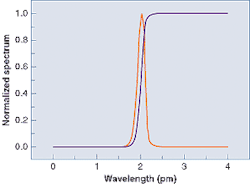
We tested this concept using a dual-chamber breadboard light source built from components of existing lithography light sources, in which the only special requirement was software to synchronize discharges in the two chambers. The measured linewidth was 0.18 pm full-width at half-maximum (FWHM) and 0.35 pm at 95% of the integrated energy, compared to single-chamber results of about 0.45 pm FWHM and 1.1 pm at 95% energy (see figure). The actual linewidth is smaller than the measurement indicates, because the data were convolved with the slit function of the metrology equipment used to measure linewidth.
James Turlo
Sr. Director, Product Marketing
Cymer (San Diego, CA)
[email protected]
