An ideal optical amplifier, like an ideal electronic amplifier, would have uniform gain across a wide range of frequencies or wavelengths. Likewise, an ideal transmission system also should have uniform response across its operating range. Real systems, however, fall short of those ideals, creating a need to equalize gain across the spectrum.
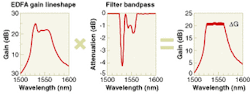
The problem with optical amplifiers is evident in the gain spectrum of erbium atoms. Erbium exhibits gain from 1525 to about 1610 nm, but this gain peaks sharply near 1535 nm, and declines at longer wavelengths (see Fig. 1). Such wide variation presented little problem in early systems that transmitted only a single optical channel through the erbium-doped fiber amplifier (EDFA). Serious issues arose, however, with the introduction of wavelength-division multiplexing (WDM). The variation of gain with wavelength meant that the channels with the least gain would fade away as they passed through a series of EDFAs.
To control this imbalance, engineers inserted static optical filters to selectively attenuate the wavelengths at which gain was the highest in order to offset the excess gain, thus balancing gain across the spectrum. This static gain equalization proved its worth in the first generation of WDM systems, but its application is limited. Minor dynamic fluctuations accumulate over long chains of amplifiers, particularly when the gain per amplifier is high, as in terrestrial systems. Furthermore, static gain flattening cannot cope with dynamic optical networks in which the channel loading changes over time when channels are added or dropped.
Overcoming these limitations of static gain equalization requires an active system that automatically provides dynamic gain equalization. Dynamic gain equalization can balance the strengths of optical channels in optical networks that switch optical channels, changing the loads on optical amplifiers. They also can balance minor fluctuations in the transmission system as well as in the optical amplifier, which can accumulate over long chains of amplifiers.
Gain equalization concepts
Dynamic gain equalization requires a feedback loop that monitors the amplifier output, then uses that information to adjust the amplifier output. This loop can simultaneously compensate for fluctuations in the amplifier and in the transmission system. The amplifier systems generally consist of two internal amplification stages, separated by a variable optical filter (see Fig. 2). A fraction of the amplified output is split to an optical monitoring system, which measures the light intensity as a function of wavelength across the spectrum. Control circuits analyze the monitor output and adjust transmission of the variable optical filter so it balances the output power across the spectrum. The network operator sees the process as automatic, and no intervention is required to keep output uniform across the spectrum.The variable optical filter dynamically subtracts power that reduces the output of the optical amplifier at certain wavelengths, balancing output across the spectrum. The feedback loop also monitors fluctuations within the transmission system, although some engineers prefer to balance transmission losses within that part of the system.
What is called gain equalization may not strictly speaking equalize the gain on all channels, because input power and/or fiber attenuation may vary as well. In practice, it is more important to equalize the output power than the actual gain. Gain leveling is often synonymous with gain equalization. Gain clamping differs subtly because—strictly speaking—it implies that the gain of the amplifier is fixed at a certain value for each channel, rather than that the output power is equalized. These terms are not standardized, so it is important to check what is meant.
Dynamic channel equalization is functionally distinct from dynamic gain equalization because the operation is performed on individual channels rather than on the overall gain curve. Channel equalization requires an optical channel monitor that measures the power on each channel. Feedback from that measurement is applied to a set of variable optical attenuators, one on each optical channel. This requires demultiplexing to separate the channels, and subsequent remultiplexing—this adds components and complexity. Dynamic channel equalization, however, can be attractive for systems that transmit only a few optical channels, or at points where the channels must be demultiplexed for other reasons, such as at a switch.
Technologies used for dynamic gain equalization
Standard optical performance monitors or optical-channel monitors can provide the information required to drive the feedback loop. An electronic stage processes these measurements and converts them into the form needed to drive the variable optical filters. The degree of processing and the nature of the outputs depend on the technology used for the variable optical filters—variable optical attenuators are similar, but their transmission normally does not depend strongly on wavelength, while that of variable filters does. Details of the processing are often proprietary.
Several technologies are used for variable optical filters. The main requirements are that they can be modulated with a large enough amplitude to meet system requirements, and that they cover the operating spectrum with high enough spectral resolution to balance the optical channels being transmitted. Response time is not yet a major issue.
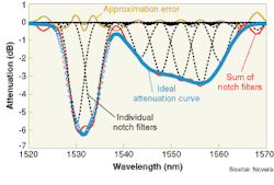
One standard approach is the acoustic-optic filter, in which acoustic waves induced in a suitable crystal diffract light waves, deflecting a certain fraction of the light in a different direction. In monochromatic versions, a single acoustic frequency interacts with one wavelength. In WDM versions, a series of independently controlled acoustic actuators generates a series of frequencies at the appropriate amplitudes. Each frequency deflects signals over a limited range of wavelengths, selectively attenuating those wavelengths. The sum of all the attenuation curves gives an overall attenuation curve, which can be varied by varying the amplitude at each frequency. The degree of resolution depends on the number of acoustic frequencies.
Modulation of eight acoustic frequencies can produce a complex attenuation profile. In a system developed by Novera Optics (San Jose, CA) the acoustic waves modulate light passing through a fiber (see Fig. 3). Alternatively, the acoustic waves can modulate light passing through bulk crystals, an approach used by Brimose (Baltimore, MD). Note that the number of acoustic frequencies can be considerably less than the number of optical channels. What matters is how they add to provide a collective attenuation curve.Other approaches are based on planar waveguide technology. One is thermo-optic modulation of transmission through an array of polymer waveguides. An initial stage such as an arrayed waveguide demultiplexes the input channels, which then are directed through separate parallel polymer guides. Individual heaters change the temperature of each guide, reducing the refractive index differential and thus increasing the attenuation. A separate multiplexer then recombines the optical channels. Gemfire (Palo Alto, CA) says a key to this approach is the high efficiency of the polymer, so 15 mW of heat can attenuate intensity by 20 dB.
Other waveguide devices are based on arrays of Mach-Zehnder interferometers with thermal heaters on one arm to modulate the phase, which the interferometer converts to intensity variation. Phase modulation generally is more efficient than intensity modulation, but the devices tend to be more complex. Combining the outputs of the individual Mach-Zehnders gives a composite spectrum.
Liquid-crystal devices also can be used as variable attenuators. One approach disperses the wavelengths in the signal linearly across a liquid-crystal device. Modulating the spatial pattern of the liquid crystal then modulates the wavelengths spread out across the cell.
Diffractive MEMS devices can serve as variable diffraction gratings. In a configuration used by Lightconnect (Newark, CA), the MEMS structure consists of two layers. One is a regular array of reflective stripes suspended above the second layer, a refractive substrate (see Fig. 4). Moving the suspended upper layer a quarter wavelength relative to the substrate shifts the phase of the reflected light 180° relative to that of light from the substrate, shifting between constructive and destructive interference. When light is spread across the array, each stripe modulates a narrow band of wavelengths, and the bands are summed together to give a variable optical filter. Silicon Light Machines (Sunnyvale, CA) uses a different diffractive MEMS approach based on moving sets of ribbons suspended above the substrate relative to each other rather than relative to the substrate; in its design the substrate does not reflect light.Conventional tilting-mirror MEMS also can be used to make variable optical filters. As with diffractive MEMS, the spectrum is spread out across an array of devices, but the tilting mirrors attenuate the signals by deflecting some of the light away from the output port.
Amplifiers and alternatives
So far most dynamic gain equalizers have been based on attenuating the stronger channels. The approach is straightforward, but anything that throws away light has the potential to increase noise.
One alternative is to use small erbium amplifiers to boost the power available on a limited range of wavelengths. In this case, the feedback would control gain of these small amplifiers.
Another alternative is to use gain-controlled Raman amplifiers. Raman gain is offset a characteristic amount from the pump wavelength, with the peak gain at 13 THz from the pump. Developers have shown that Raman amplifiers pumped simultaneously at several wavelengths have more uniform gain profiles. By adjusting the relative powers of these pump lasers, RedC Optical Networks (Tel Aviv, Israel) can vary the gain profile of the Raman amplifier, offering a different road to dynamic gain equalization.
The diversity of approaches to the problem of dynamic gain equalization is good news. Yet developers of each approach inevitably cite limitations of the competing technologies. If anything is clear, it's that the technology for dynamic gain equalization remains far more complex and less mature than static gain equalization. A new generation of high-performance dynamic optical networks is likely to require some active form of gain equalization, but it remains unclear when that new generation will arrive and exactly what its requirements will be.
ACKNOWLEDGMENTS
Thanks to Eric Gustafson of Lightconnect, Nigel Cockroft of Gemfire, and Uri Ghera at RedC Optical Networks.

Jeff Hecht | Contributing Editor
Jeff Hecht is a regular contributing editor to Laser Focus World and has been covering the laser industry for 35 years. A prolific book author, Jeff's published works include “Understanding Fiber Optics,” “Understanding Lasers,” “The Laser Guidebook,” and “Beam Weapons: The Next Arms Race.” He also has written books on the histories of lasers and fiber optics, including “City of Light: The Story of Fiber Optics,” and “Beam: The Race to Make the Laser.” Find out more at jeffhecht.com.


