CUSTOM OPTICS: DUV nanolithography enables advanced diffraction-grating arrays
CHRISTOPH M. GREINER, THOMAS W. MOSSBERG, AND DMITRI IAZIKOV
The technology for manufacturing diffraction gratings has not seen significant change for more than 40 years. Diamond scribing with ruling engines and interference lithography (holographic fabrication) have dominated grating fabrication. Both approaches constrain available grating patterns to fairly simple line structures. As a consequence, advanced-function gratings that require variable line spacing, general curvilinear line contours, or spatially accurate combination of multiple dissimilar gratings have received only limited attention. This situation is changing, however.
Courtesy of deep-ultraviolet (DUV) reduction photolithography-the workhorse tool of the semiconductor industry-it is now possible to nanopattern essentially arbitrarily structured gratings close to 10 cm2 using sub-100 nm pixels and nanometer-scale placement accuracy. Deep-UV lithographic fabrication enables gratings with features such as flat-substrate focusing/imaging of dispersed signals,1 aberration correction, new blazing mechanisms, and multiple coherent diffractive sections with differing line spacing, orientation, and curvature.
Examples of advanced-function coherent grating arrays include sets of grating regions that differ in line density and line orientation, so as to fill the output plane with multiple dispersion lines and useful spectral calibration information.
Diffraction gratings with integral wavelength calibration
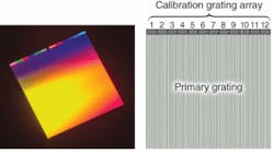
One example of such a grating is a monolithic silicon-substrate diffraction-grating array consisting of a single primary 1200 lines/mm grating and 12 auxiliary gratings at the top of the substrate (see Fig. 1). When they are illuminated by a monochromatic reference, the 12 small gratings provide a family of wavelength-calibration markers in the grating’s focal-plane detection region. These markers allow highly precise and convenient wavelength calibration of the primary grating’s dispersed output.
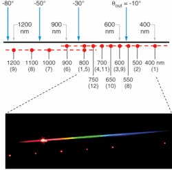
This function can be illustrated schematically and visually (see Fig. 2). The output signals of the primary grating and calibration array in the system’s detection (focal) plane are depicted schematically (Fig. 2, top); white-light illumination is assumed. The wavelength numbers above the horizontal line were obtained by the grating equation for the primary grating.The output marks of the calibration gratings are shown as red circles. These features are obtained by illuminating the calibration array with a HeNe laser copropagating along the standard input direction. The marker spots occur at precisely determined intervals on two horizontal lines parallel to the primary grating dispersion line. The wavelengths given below these horizontal lines indicate the wavelength that the primary grating diffracts to the location of the calibration marks. In combination with appropriate detection, such as a two-dimensional (2-D) photodetector, the calibration array thus allows one to fully calibrate the primary grating’s dispersion line for its entire spectral region with only a single reference source.
Intriguingly, the calibration-marker wavelength values obtained for a given reference do not depend on the input angle to the grating. While the detection-plane pattern changes with input angle, the correlation between each marker point with the its primary grating output wavelength is preserved. Other reference light sources can be used as well, which enables one to change the calibration-marker wavelength values.
An immediately noticeable feature of the calibration gratings in Fig. 1 is that their grating lines exhibit a nonzero tilt with respect to the substrate vertical that is different for each grating. Tilting the grating lines rotates the calibration grating’s dispersion planes. Gratings of different tilt produce dispersed outputs that are angularly and thus vertically displaced from each other. This effect, combined with appropriate line densities, is used to position the calibration-wavelength markers parallel to the primary grating’s dispersion line.
Wideband monolithic grating arrays
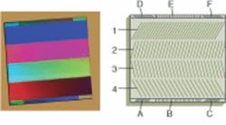
In a different type of grating array, four primary gratings designed to have slightly overlapping active spectral ranges occupy a single substrate (see Fig. 3). Auxiliary gratings at the top and bottom of the substrate produce optical outputs used for wavelength calibration and system alignment.Instantaneous and contiguous access to optical bandwidths multiple times that of a single grating is provided, but with the same spectral resolution. This feature makes wideband grating arrays particularly advantageous for spectroscopic applications in which substantial optical bandwidths have to be acquired in a single shot or on time scales inconsistent with slow mechanical-grating rotation.
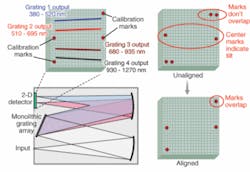
While the use of a monolithic grating array simplifies the Czerny-Turner design by eliminating the rotating grating turret, further reduction of system-component count can be achieved by designing the collimation and focusing function of the two spherical mirrors into the array gratings themselves. Such array gratings that focus an incident signal onto the 2-D detector while spectrally dispersing it can be conveniently designed via computer-generated holography. The grating pattern is simply derived from the interference pattern computed between desired input and output beams and then realized via photolithography and etch.1 A reduction in the number of system components is desirable in terms of cost, as well as system footprint/compactness, ruggedness, and insensitivity to perturbations in the instrument’s environment such as temperature and vibration.
Array alignment and output calibration
Six small gratings at the top and bottom of the grating array of Fig. 3 provide marker signals that, when mixing a reference source into the system input, allow one to spectrally calibrate the primaries’ output, as well as aid in system alignment. When the detector surface properly coincides with the focal plane of the post-array focusing mirror, two pairs of the six alignment marks are designed (via identical line tilt and line density) to produce overlapping output spots on the detector. Two center marks originating from the remaining two gratings (without line tilt) enable correct horizontal alignment of the array and the detector surface.
At the same time, left and right reference marks indicate the beginning and end points of the spectral coverage provided by the primary gratings and allow the user to calibrate wavelength versus position along the primaries’ dispersion lines (with calibrated wavelength range independent of the input angle). When combined with an appropriate feedback routine, the spectral calibration and alignment features comprise inherently intelligent references that allow for fully automatic grating-detector alignment, correction, and spectral-range calibration, making gratings with reference/calibration structures ideally suitable for implementation in hostile or difficult-to-access environments where essentially autonomous system function is highly desirable.
Inner workings of the array gratings
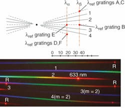
Similar to the calibration gratings in Fig. 1, the primary gratings in Fig. 3 have a nonzero line tilt to displace their respective dispersion planes from each other (see Fig. 5). The solid black dot in the schematic is the extrapolated intersection point of all the dispersion planes (solid lines), and indicates the specular reflection (zeroth order) output common to all gratings. The primaries’ line densities are different and chosen so that the four gratings produce contiguous spectral coverage over approximately a factor of three in wavelength in the four separate output stripes within a predetermined output angular range. A photograph of the far-field grating-array output for white-light input and a HeNe reference source clearly shows the bright red HeNe calibration marks. Alternative reference wavelengths can be used to change the wavelength spans bracketed by the calibration-output markers.As these examples demonstrate, the introduction of new and advanced fabrication tools into the important area of gratings and more generally diffractives promises to unleash a torrent of innovative design.
REFERENCES
1. C.M Greiner et al., Optics Express14, 11952 (2006).
Tell us what you think about this article. Send an e-mail to [email protected].
CHRISTOPH M. GREINER and DMITRI IAZIKOV are senior scientists and THOMAS W. MOSSBERG is president of LightSmyth Technologies, 1720 Willow Creek Circle, Suite 520, Eugene, OR 97402; e-mail: [email protected]; www.lightsmyth.com.
