ASPHERIC OPTICS: Distributing aspheric surfaces brings down cost
Robert Smith’s A Compleat System of Opticks (Cambridge, England, 1738) has a chapter on ideas for the fabrication of aspheric optical surfaces “without the assistance of a fortune which could well bear the disappointment.” In fact, it is 350 years since scholars including James Gregory and Isaac Newton discovered the advantages of parabolic, ellipsoidal, and hyperbolic profiles for telescope mirrors. It was not until ten years after Gregory’s first attempts to make what we now call a Gregorian telescope, however, that Robert Hooke finally succeeded in fabricating an adequate parabolic primary mirror. At the time, Baruch Spinoza wrote in relation to a newly proposed optical fabrication process, “experience has taught me sufficiently that, in spherical tools, it is safer and better for glasses to be polished with a free hand than by any machine.”
While the area of aspheric optics has since seen many technical innovations, it is astonishing that it continues to hold similar challenges for current technologies. However, computer-controlled machines, the next step in this extraordinary journey, are finally removing the traditional requirement for artful manual polishing of aspherics.
Moving to modern approaches
The well-known performance gains delivered by aspheres have often remained just beyond practical reach. One design strategy has been to analyze an all-spherical design to identify the surface that contributes significantly to the aberration so that that particular surface can then be aspherized. Alternatively, it is not unusual for aspheric surfaces to be introduced as heuristics early in the design process to uncover new design forms.
Ultimately, however, the number of aspheric surfaces is reduced by as much as the associated performance degradation allows. Such processes often lead to aspheres with hundreds of waves of departure from a best-fit sphere, or even more. The relative difficulty of fabricating and testing glass aspheres has meant that they have traditionally been restricted to domains such as leading-edge (in Smith’s terms, “fortune-assisted”) systems, or high-volume molded elements. For run-of-the-mill jobs, optical shops until now have been unable to accommodate the cost and lead time required for dedicated null optics, nor the expense of time-consuming fabrication and assembly steps. However, deterministic computer-controlled generating and finishing technologies continue to transform the world of optical fabrication. What’s more, they have recently been supplemented by a new approach to asphere metrology that leads to novel strategies for cost-effective designs incorporating milder aspheres.
Interferometric stitching
Subaperture-stitching interferometry was originally developed to allow small reference flats to provide complete tests of larger optical flats, or of large-clear-aperture parabolas in double-pass autocollimating mode. By registering a collection of separate measurements in their regions of overlap while compensating for the unknown amounts of piston and tilt in each subaperture, this process can obviously also boost the transverse resolution in the stitched metrology as a bonus to the aperture gain. However, this simplistic uncalibrated implementation comes at the cost of reduced accuracy due to the associated “stitching errors.”
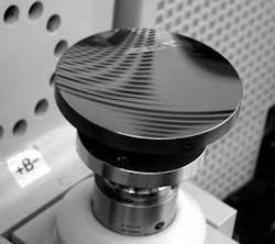
More recently, a computer-controlled stitching interferometer was commercialized for testing spherical parts.1, 2 By using algorithms that exploit the apparent redundancy in the multiple measurements, this fully automated system can actually yield higher accuracy than conventional full-aperture tests. Aside from the familiar compensation for errors arising from part motion, these systems use the overlapped data to resolve consistent errors such as reference-wave error and image distortion. Stitching, therefore, now provides a cost-effective automatically calibrated solution for accurately testing a wide range of high-numerical-aperture (NA) and/or high-clear-aperture (CA) parts by using no more than off-the-shelf reference optics (see Fig. 1).
With appropriate generalization of the compensation and in-line calibration processes, stitching can also cope with increased aspheric departure while correcting for aberrations (that is, non-common-path effects) within the interferometer optics.3 In fact, it was recently reported that this type of automatic-stitching interferometer is now playing a critical role in mid-spatial-frequency metrology on the steep aspheres in systems under development for EUV (extreme-ultraviolet) lithography.4 In particular, they are currently used to cover the “no man’s land” in spatial frequencies that lies between the domain of interference microscopes and that of conventional figure-measuring interferometers with their associated null optics. Remarkably, the repeatability of the resulting stitched measurements is better than 0.1 nm root mean square (rms) over the band of [0.33, 5.0] cycles/mm.
Such outstanding results rely crucially on the automatic calibration that has been absorbed as a key part of the stitching itself. This system elegantly exploits the simultaneous gains now offered by stitching interferometry in terms of resolution, accuracy, and aspheric departure; the old notion that stitching errors are always a critical limitation has resoundingly been placed alongside Gregory’s disappointment with his primary mirror. It should be emphasized that there are no null optics in the stitching interferometer; this lack of dedicated correctors means that the systems are as versatile as conventional spherical-test setups.
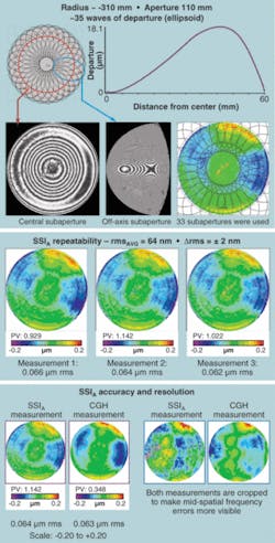
The same process can, of course, be used to perform full-aperture figure testing of aspheric optics.5, 6 Apart from the aberration correction, the gains in testable aspheric departure follow chiefly from the increased resolution in each subaperture and from the option of finding a locally optimal null (see Fig. 2). In this example, the test was completed in less than 15 minutes and was repeatable at the 2 nm level. Although this example demonstrates the benefits of stitching interferometry on a surface with approximately 35 waves of aspheric departure, flexible test capabilities for aspheric departures exceeding 100 waves are possible. When coupled with deterministic subaperture tools, these metrology systems enable flexible production of moderate aspheres.Design processes and examples
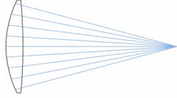
Significantly enhanced fabrication capabilities generally warrant a reinvestigation of design studies and processes that are consistent with the new manufacturability and tolerancing constraints. To help make the case for distributed, mild aspheres, let’s look at two examples using the Zemax optical-system-design software. The first is a simple f/2 singlet lens (see Fig. 3).Optimizing this as an all-spherical surface design yields an rms spot radius of almost 400 µm and large amounts of spherical aberration. Because spherical aberration varies as the fourth power of the lens aperture, the traditional method to improve performance (while retaining the singlet design) is to make one surface an asphere in which the departure from sphericity is a function of the fourth power of the lens aperture (in other words, an even asphere in which the r4 term is the variable). This gives substantial improvement; the rms spot radius shrinks to just over 8 µm.
The devil, however, is in the details. The resulting surface is extremely aspheric; the maximum difference between the aspheric surface and the best-fit sphere is on the order of 200 waves. This makes the surface difficult to make and test, and almost certainly very sensitive to any manufacturing error.
A better technique is to allow both surfaces of the singlet to become aspheric, but constraining them so that the maximum deviation between the aspheric surface and the best-fit sphere is limited (in this case) to less than 80 waves. The Zemax BFSD (best-fit-sphere-data) optimization operand is ideal for this task. The resulting design has an rms spot radius of less than 6 µm, with a maximum deviation from the best-fit sphere of about 60 waves-better performance and, at the same time, more manufacturable.
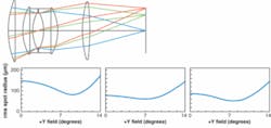
Replacing single highly deviant aspheres with distributed, milder aspheres is generally a good strategy for making designs more manufacturable. As an example of a more-complex case, consider the celebrated double-Gauss camera lens (see Fig. 4).A good metric of performance is the polychromatic rms spot radius as a function of the field of view of the lens. Allowing the surface nearest the stop to become an r4 asphere to help control the spherical aberration gives a big improvement, but at the cost of adding a single, highly deviant asphere (more than 200 waves of departure from the best-fit sphere). Distributing the asphericity between the surface nearest the stop and the surface furthest from the stop, and restricting the maximum aspheric deviation to be less than 90 waves gives almost identical performance. By understanding the practical manufacturing and testing limits and constraining the critical parameters, the designer can dramatically impact the viability of their design. In this example, it will be faster and cheaper to produce two aspheres with fewer than 90 waves of departure, than one asphere with more than 200 waves of departure. Thousands of dollars are saved simply be avoiding the need for a dedicated null lens (required for testing the surface with a 200-wave departure).
Distributed, milder aspheres open new doors
Just as all manner of machines have progressively replaced Spinoza’s preferred “free hand” for the fabrication of spherical optics, computer-controlled tools continue to evolve for fabricating aspheres with similar flexibility. As always, such evolution necessarily involves interplay between design, fabrication, and testing. Recent steps in metrology have meant that 100-wave aspheres are now far more cost-effective. The simple design examples discussed above indicate the impact mild aspheres can have when they are spread through the system and existing design tools are capable of imposing the appropriate manufacturing constraints. All that is left is to create awareness throughout the design community of the practical optical-fabrication and testing limits for high-precision glass aspheres. Limiting aspheric departure to fewer than 100 waves and distributing asphericity on multiple surfaces throughout the system is currently a useful rule of thumb for designers that can significantly reduce cost and lead times for aspheres.
ACKNOWLEDGMENT
The authors thank Mike DeMarco, Don Golini, Ken Moore, Paul Murphy, and Marc Tricard for their contributions to this article.
REFERENCES
1. P. Murphy et al., OPN Magazine (May 2003).
2. J. Fleig et al., Proc. SPIE 5188, 296, SPIE, Bellingham, WA (2003).
3. US Patent 6,956,657
4. M. Ohtsuka, Frontiers in Optics, Laser Science, Optical Fabrication and Testing and Organic Photonics and Electronics 2006 (Optical Society of America, Washington, D.C., 2006) OFWC1.
5. P. Murphy et al., Frontiers in Optics, Laser Science, Optical Fabrication and Testing and Organic Photonics and Electronics 2006 (Optical Society of America, Washington, D.C., 2006), OFWC2.
6. J. Fleig and P. Murphy, Frontiers in Optics, Laser Science, Optical Fabrication and Testing and Organic Photonics and Electronics 2006 (Optical Society of America, Washington, D.C., 2006), OFTuA6.
Greg Forbes | Senior Scientist, QED Technologies
Greg Forbes was on the faculty of the Institute of Optics at the University of Rochester for about ten years until the mid 1990s. He returned to Australia as a Research Professor in Physics at Macquarie University in Sydney. For the last ten years he has been Senior Scientist at QED Technologies. He lives in Sydney but regularly comes to visit and work with his colleagues and friends in Rochester.
Mark Nicholson | Vice President of Operations, Zemax
Mark Nicholson is vice president of operations at Zemax (Kirkland, WA).


