AXEL HUELSMANN, INGO BUECHNER, AND ULRICH VAN GEMMEREN
Lasers are widely used as structured light sources in machine-vision applications. Structured light is light that is shaped into a geometrical pattern such as a dot, dot matrix, line, grid, circle, or other pattern. Incidence of structured light on an object under a defined angle to the optical axis of the imager (typically a CCD or CMOS camera) leads to the deformation of the light structures. From the value and form of the deformation, height information about the object can be obtained.
The structure can be a zero-dimensional form using a dot, as in laser triangulation; a one-dimensional form using a line, as in laser light section; or a two-dimensional form using a grid or a line-stripe light structure, as in the grid projection method.
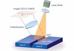
In laser light section, profiles are determined by recording the surface structure with lines, enabling the user to determine a height profile along a projected laser line. When the beam direction and the distance between camera and laser are known, the height profile along the line on the object can be exactly calculated (see Fig. 1). By moving the measuring line continuously across the object, the object’s surface structure can be determined with high precision. Depending on the angle of the incident light, the measuring resolution varies: a large angle results in a high resolution but a small leveling (horizontal line of sight) area, while a small angle reduces the resolution but increases leveling area.
Line-generator optics
The accuracy of any measurement using structured light is strongly affected by the quality of the laser and its optics. For single-profile measurements a laser line is sufficient with laser powers ranging from 5 to 100 mW. Depending on the application, several line parameters are important for the precision of the measurement. First, the intensity profile in the direction of propagation of the line should be homogeneous. The line should be absolutely straight, and the profile perpendicular to the line propagation should be Gaussian to achieve subpixel resolution using a Gaussian line fit. Finally, the profile perpendicular to the line propagation should have no or only very low side lobes, and width should be thin and homogeneous over the whole line.
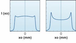
The homogeneity of the line intensity in the direction of its propagation is determined by the curvature of the line-generator lens. For lines with homogeneous light distribution, so-called Powell lenses are used (see Fig. 2). These lenses are handcrafted and each lens must be individually checked for homogeneity of the intensity. A simulation by calculation can yield drastic inhomogeneities even with small changes in curvature parameters, resulting in a noisy intensity distribution along the line, with variations in the range of 15% not unusual.In high-resolution measurements of objects with very small structures, side lobes-an effect created by imperfect line-generator optics-disrupt the Gaussian profile and produce a clutter that disturbs the measurement. In addition, lines must be absolutely straight for accurate measurement of the deformation of objects under test. Low-cost line-generator products are often bent or have an “S” shape.
To measure the line straightness over the entire working length of the measurement line, the laser can be rotated ±90° in front of a line camera, and intensity and position data can be recorded as a function of the rotation angle. The line width and the intensity distribution over the entire line can also be measured.
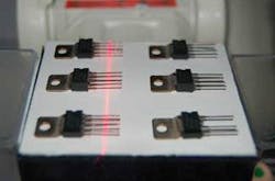
Optimal sharpness of the laser projection at a given object distance is important for all applications (see Fig. 3). Typically, fine lines are used to achieve a good spatial resolution and the laser optic should be focused by hand and then secured in position for optimal projection quality for the particular application. To avoid errors in measurement, the position of the projection should not be shifted during focusing.Dot optics
Dot projections are suitable for simple presence check and height measurements. In many cases the shape of the dot is not important and elliptical shapes are used. For round dots, laser diodes with integrated micro-optics give ellipticities of better than 0.9 (close to perfectly round). Multiple dots such as a dotted line can be used to determine the flatness of objects. If calibrated on a perfectly flat plane, the smallest shift in the position of any dot indicates measurable imperfections in flatness.
Diffractive optics
In addition to point and line structures, several other projection patterns are used in machine vision: crosses, circles, dot matrices, multilines, and grids. Diffractive optical elements (DOEs) are based on the principle of light diffraction on periodic microstructures. By selective computer design of the surface structure beam-shaping properties, DOEs can be fabricated as computer-generated holograms or free-form phase functions (see Fig. 4).Cost-effective manufacturing of DOEs is achieved by replicating a master (generated by electron-beam direct-write lithography) on polymer or glass substrates. The quality of the projection depends on the quality of the computer-generated hologram (depending on the algorithm), as well as on the master and the replication process.
Band and polarization filters
Because laser light is monochromatic, band filters can be used in machine-vision applications. These interference filters can block all light except for a small wavelength band that can pass, allowing only a particular portion of the laser light to be observed. And because diode lasers send out linearly polarized light, intensity-reducing polarizers are not required to remove disturbing reflections; instead, the polarization plane can be rotated to eliminate almost all unwanted reflected light (see Fig. 5). If a dot matrix of 40 × 50 dots with an intensity of 0.5 mW per dot is required to characterize, for example, the three-dimensional form of an object under ambient light conditions, a 1 W laser can be used.Other important laser parameters
For precision measurements, it is important to control the power, wavelength, and pointing stability of the laser. Fortunately, laser light can be easily focused, resulting in high light density for sharp and intense dots, lines, and other patterns without high power consumption. However, temperature changes can produce a change in the refractive index of the optics and a change in the wavelength of the laser, resulting in a change of the line position. Such changes are small but measurable and can sometimes be ignored, depending on the accuracy requirements of the application.
For applications at room temperature, automatic power control (APC) for diode lasers and photodiode feedback control for diode-pumped solid-state (DPSS) lasers is normally sufficient because the wavelength change resulting from a change in temperature is approximately 0.019 nm/°C. Applications under high, low, or drastically changing temperatures, however, require active temperature control of the laser using thermoelectric cooling. A good thermal design will ensure good heat transfer from inside the diode to its outside package and excellent temperature control within a wide ambient temperature range.
For synchronization with the camera pixel readout (such as for dynamic measurement of moving objects) the lasers must be modulated in the megahertz range. If the laser is in stand-by mode and will be switched to full power within a few microseconds, it is important that the transient response is very fast and the fish tails are small.
AXEL HUELSMANN is research and development manager, INGO BUECHNER is special laser product manager, and ULRICH VAN GEMMEREN is general manager at Z-Laser Optoelektronik, Merzhauser Str. 134, D-79100 Freiburg, Germany; e-mail: [email protected]; www.z-laser.com.


