HAL KÜHN
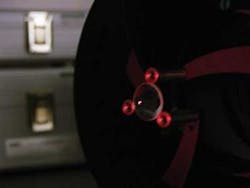
A decade ago, aspheric optics were used in only the most demanding applications due to the fabrication difficulties and the subsequent costs. These were typically low-volume, specialty applications. The continued development of molding technology over the past ten years has significantly reduced the costs of aspheric optics and allowed their use in more broad and cost-conscience applications. Today, aspheric optics are manufactured with high precision at high volumes, in a range of sizes, for applications including traditional optics, fiber-optics, photonics, and even consumer applications (see Fig. 1). Despite the significant improvements in molding technology, some important design considerations still remain that are critical to the manufacturing process and the overall performance of the molded aspheric lens.
The precision molding process
The precision molding process begins with fabricating a set of molds with the required aspheric curvatures. Numerous techniques are used to fabricate these molds; the end result should be a pristine curve with power and form error less than the target values for the molded lens. The next step is the fabrication/procurement of a preform of the requisite glass. The term “preform” is a generic term for the glass in its premolded form. This form can take on a variety of shapes depending on the lens being fabricated and the process being used. The preform size and shape need not concern the customer; rather it is a design consideration for the manufacturer, based on the lens requested and the intricacies of processing.
Next, the glass preform is heated and pressed between the two molds. The molding variables such as time, temperature, and applied force are controlled to produce lenses of the required performance. The specific molding parameters are not generally published because they are an integral part of the manufacturers’ intellectual property. The end result of this process is a lens that does not require any additional processing, with the possible exception of edging to the target diameter. After this, the lens can be coated with a variety of optical coatings to meet the specific demands of the application. Using this process, lenses of various sizes and shapes can be fabricated. For example, Archer OpTx can produce ultrahigh-precision aspheric and biaspheric lenses from 0.3 to 55 mm in diameter in all popular formats, including plano/convex, biconvex, or meniscus.
Design considerations
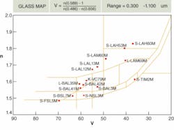
When considering custom-molded aspheric optics, the most important piece of advice that we give to customers is to consult with our engineering staff early and often during the design process. One limitation regarding lens shape is that, with the exception of very small lenses (less than 1 mm), the preferred format is a round outside diameter. Square or rectangular lenses are not desirable for direct molding. These types of lenses can be provided with post-molding processing but will not be as cost-effective as their round counterparts. Also, lenses with 90° corners, notches, or other features should be avoided. Again, these do not lend themselves well to direct molding but can possibly be fabricated through post-molding processing techniques. The molding process lends itself well to the vast majority of aspheric curvescurves approaching hemispheres, however, should be avoided. Also, lenses with extreme aspheric departure, significant inflections, or free-form lenses without rotational symmetry should be avoided. In addition, the aspect ratio of the lens (thickness to diameter) should be less than or equal to 1.Glass selection is an important consideration. The optical properties of a specific glass (refractive index, dispersion, dn/dt, and so on) have a significant impact on optical design. When designing a molded aspheric lens, a few additional considerations need to be addressed. First, molded asphere manufacturers typically have a glass offering significantly less than that of the major optical manufacturers. Some manufacturers offer only a few glass choices due to processing limitations. A manufacturer should offer at least a dozen different standard optical glasses distributed throughout the glass map (see Fig. 2).
We recommend that designers select a glass from the manufacturers’ glass list. The reason for this is twofold. First, to provide the best optical performance, the design should consider the post-molded refractive-index values. These values should be provided by the molded-asphere manufacturer, and are different from the values provided by the optical-glass manufacturer. The refractive index changes as a result of the molding process. Second, the manufacturer has already verified the glass compatibility with its molding process.
Glasses that are not available on the approved glass list can still be molded at the discretion of the manufacturer, but will be more expensive.
Tolerancing
A correct understanding of tolerances is crucial to robust design. Key tolerances that affect lenses are wedge and decenter. These two errors are equivalent for spherical optics. For aspheric optics they must be considered individually. Power and irregularity are replaced by power and form error tolerances. The power is specified as a sag error from design; for lenses with a nonzero conic, it is necessary to calculate the radius error that maps to the sag error. Form error is the deviation (radial and azimuthal) from the target shape; the error is typically specified as a maximum value (P-V error). The modeling technique to estimate the allowable tolerances involves applying a surface perturbation of the appropriate spatial frequency and amplitude. Tolerance analysis using the asphere coefficients do not model real-world errors and contain no useful information.
Designers should make every effort to use the DIN/ISO even-asphere model whenever possible. This equation takes into consideration the base radius and radial coordinate of the lens and the conic constant. This model description is readily transferable to computer-numerical-control optical manufacturing and surface-profiling equipment and provides a common understanding between the customers and vendors.
The performance of a molded aspheric lens is typically tested in one of two ways. The first is a root-mean-square (rms) transmitted wavefront measurement of the lens at 632 nm using an interferometer. In the event the design/operational wavelength of the lens is different from the test wavelength, the performance of the lens at the test wavelength will be modeled using optical-design software to provide a direct performance comparison. The second method is the use of a high-precision contact profilometer to measure the actual surface of the molded lens and compare it to the aspheric coefficients of the design. From this measurement, the magnitude of power and form errors can be determined. This technique can also be used to measure the surface roughness of the lens, among other things. Equipment used for spherical optics can also measure additional parameters such as dimensional tolerances, effective focal length (EFL), and back focal length.
Anticipated performance
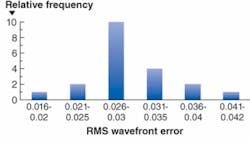
Adhering to the guidelines outlined will enable fabricated aspheric lenses to achieve exceptional performance. For example, our proprietary PerfectLens molding process produces the L240 lens with a diameter of 9.95 mm, an EFL of 8 mm, and 0.5 NA. Whereas the rms wavefront specification is less than 0.05 waves, the actual wavefront achieved is lower than any other lens by nearly a factor of two.In a histogram of a random sample of L240 lenses, several essential features stand out (see Fig. 3). First, the average performance is approximately 0.03 waves. Second, the distribution is approximately Gaussian. More important, the histogram does not show truncation, which is the result when quality is “inspected in” and good lenses are culled from bad. Finally, the distribution is well-controlled with respect to the specification limit. This is crucial because the process control is what makes consistency and repeatability an innate characteristic of the product. Finally, the fact that meeting the specifications is not a challenge equates to plentiful, reliable production.
Precision glass molding processes allow the use of standard optical glasses that offer a low coefficient of thermal expansion and are compliant with the Restriction of Hazardous Substances Directive. The high lens-to-lens uniformity and high optical performance save cost through reduced need for quality inspection and production labor, and reduced variability in the final product. As such, precision molding is the best option to manufacture stable and repeatable, high-performance optics.
Hal Kühn is president of Archer OpTx, 3402 Enterprise Drive, Rowlett, TX 75088; e-mail: [email protected]; www.archeroptx.com.

