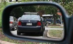
Just as a flat mirror is a nonimaging optic, so are most free-form reflectors. And, just as a flat mirror can be a very important visual aid, so can a properly designed free-form reflector. R. Andrew Hicks, a researcher at Drexel University (Philadelphia, PA), has proved this to be true by developing an automobile rear-view mirror that has a field of view more than twice as wide as that of a conventional flat rear-view mirror; and, unlike the spherical mirrors that are sometimes used in attempts to eliminate blind spots, the mirror designed by Hicks introduces almost no distortion to the field of view (see figure).1
Hicks started with the problem of designing a reflector to control a single ray bundle, in which all rays in the bundle originate from the same point. The rays all reflect once from the reflector and end up striking a target surface. The task of the reflector is to direct each ray in the bundle to a specific pre-assigned point on the target surface. Previously, Hicks determined that in most cases, there is no exact mathematical solution; however, approximate solutions can sometimes be of value.2
A flat rear-view mirror normally has a field of view somewhere around 15° to 20°. The mathematical transformation that the free-form equivalent must perform is a simple scaling (with the assumption that the angle between the reflector’s central incoming and outgoing rays is 65°). Hicks determined that if the scaling constant is too high, distortion is unavoidable, but for a field of view of up to 45° the amount of distortion is minimal.
Not a simple surface
The shape of the resulting surface is hard to describe, notes Hicks. “It’s generated by solving some differential equations numerically, which give a collection of points on the surface,” he says. “I then fit a polynomial to this, which is generally of high degree. So I can’t say that it is like some familiar surface.” The prototype reflector was fabricated on a Moore Nanotech 500FG Freeform Generator (B-Con Engineering; Nepean, Ontario, Canada).
Hicks is working to extend his calculations beyond the single-ray-bundle assumption, and is also now working on the use of free-form design for illumination systems. “My general area of research is to find efficient methods for optical design (especially free-form surfaces) by applying methods from differential geometry,” he says.
REFERENCES
- R. Andrew Hicks, Optics Lett. 33(15) 1672 (Aug. 1, 2008).
- R. Hicks, J. Opt. Soc. Am. A 22, 323 (2005).

John Wallace | Senior Technical Editor (1998-2022)
John Wallace was with Laser Focus World for nearly 25 years, retiring in late June 2022. He obtained a bachelor's degree in mechanical engineering and physics at Rutgers University and a master's in optical engineering at the University of Rochester. Before becoming an editor, John worked as an engineer at RCA, Exxon, Eastman Kodak, and GCA Corporation.
