Richard G. Allen and Lee R. Dettmann
Rarely is it possible to buy an off-the-shelf software package to monitor and control a manufacturing process. The primary reason is that the parameters that have most influence on quality usually differ dramatically from process to process. In fact, they are often unknown and must first be identified before they can be controlled in real-time processing.
The Steward Observatory Mirror Lab at the University of Arizona (Tucson, AZ), for example, is currently casting and polishing a series of Pyrex honeycomb telescope mirrors with diameters up to 8.4 m. Two years ago, the lab decided to devise a monitoring system to identify and help eliminate detrimental drag conditions during polishing. Its goal was twofold: to learn which parameters play a significant role in the glass removal rate and then to attempt to control them.
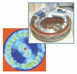
FIGURE 1. Phase map shows removal that occurs during the first 20 s of a simulated polishing run made with pitch and rouge for the test lap equipment (see inset). Removal has been magnified 1800 times for clarity.
A way of monitoring the drag forces on the lap during polishing has since been developed. Measurements of these forces are now helping researchers to predict glass removal and detect anomalous conditions that could create a significant figure error in a partially finished mirror. A key first step in identifying the significant process parameters involved the creation of a test facility for comparing glass removal to lap drag under controlled conditions on smaller mirrors. These experiments have shown that glass removal is proportional to the input frictional energy under a wide range of conditions.
The polishing process
Mirrors produced at the lab have extremely short focal lengths for their diameters and are highly aspheric.
The mirrors are polished face up with a 1.2-m deformable lap on a large optical generating machine. The motorized spindle of this machine connects with the lap via three arms that keep the lap centered under the spindle while allowing it to tip and tilt. Loadcells in the arms send force data to a Sun Microsystems (Palo Alto, CA) workstation. This computer serves as an interface to three computers that control the polishing machine with VxWorks, a development and execution software environment for building complex real-time and embedded process applications from Wind River Systems (Alameda, CA).
Polishing pressure and lap moment are controlled with three cables that run from the lap to the spindle. Additional actuators bend the lap into a shape that matches the profile of the surface that is being worked into the glass. Drag forces on the lap are not controlled. The machine simply moves the spindle. Friction, gravity, and inertia dictate the forces that are used to move the lap. Mechanical energy for polishing the mirrors is supplied by the motors that drive the mirror and lap spindle. Most of this energy is ultimately dissipated as frictional work.
During a polishing run, the process-monitoring system computes the frictional work once every second from loadcell forces and information on the position and velocity of the lap and mirror. To realistically estimate the distribution of frictional power, however, it is necessary to generate a two-dimensional (2-D) distribution of the frictional power under the lap. This could be done in several ways, but the lab accomplishes the task by simulating the lap as a randomly oriented hexagonal array of 37 small laps. Each small lap is given a weighted share of the total frictional energy. When the drag coefficient is independent of velocity, the correct weight function is the velocity of the particular lap with respect to the glass. When the drag coefficient varies with velocity or position, a more-complex weight function is necessary.
Lap drag tests
Polishing experiments on a 12.5-in. mirror have been used to develop an understanding of the factors that have an effect on lap drag (see Fig. 1). The test equipment has three vertical levers holding a 9.5-in ring lap on the mirror as it rotates underneath. Nothing else moves. One end of each lever pulls on a post mounted to the lap. The other end pushes against a loadcell that measures the force.
A link between the lap and lever eliminates vertical forces that might affect the drag. Any number of pitch or polishing pads can be mounted on the underside of the lap. Weights are used to adjust the polishing pressure. A PC with a Data Translation (Marlboro, MA) data-acquisition board monitors the signals from the loadcells. Sample programs supplied with the board were modified to display and record data every second.
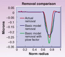
FIGURE 2. The basic model assumes the drag or frictional coefficient is independent of lap speed and position. The plow factor model assumes there is extra removal at the leading edge of the lap.
The lab measures the radial profile of the mirror with an interferometric test after each polishing run. Because each test begins with a workpiece with a smooth spherical surface, glass removal is easy to measure.
Experimenters then compare simulated profiles that are based on the drag measurements to the interferometric profiles (see Fig. 2). The basic model assumes that the Preston's Constant is really constant or that, equivalently, drag or frictional coefficient does not vary with lap speed and position. Researchers also developed a plow factor model in which there is enhanced removal at the leading edge of the lap. Both models assume that 16 ergs of frictional energy are necessary to remove a cubic micron of glass. The actual removal profile appears to lie somewhere between the two cases.
The lap drag experiments showed that the drag coefficient and its close relative, Preston's Constant, are far from constant in the real world. The drag on a pitch lap, in particular, depends on conditions such as temperature, polishing pressure, and fit to the glass. Each combination of compound and substrate, however, appears to have a characteristic efficiency that can be used to estimate glass removal from measures of the frictional work. With this and related information, the lab now has a foundation to monitor and control the polishing process in almost real time.
RICHARD G. ALLEN and LEE R. DETTMANN are researchers at the Steward Observatory, University of Arizona, Tucson, AZ 85721; e-mail: [email protected] or [email protected].

