STEVE GRANTHAM, CHARLES TARRIO, SHANNON B. HILL, AND THOMAS B. LUCATORTO
The features on integrated circuits continue to shrink according to Moore’s Law. This shrinking also applies to the wavelength of light used in the lithography process that patterns the wafer. Critical layers in leading-edge chips are now made using 193‑nm light in the middle of the deep-ultraviolet (deep-UV) spectrum. Deep-UV lithography, which uses mostly fused-silica optics, is predicted to be capable of producing features on the order of 45 nm-significantly below the Rayleigh limit-with the aid of immersion techniques and phase-shifting masks. The most likely candidate to succeed deep-UV lithography is the “next-generation” extreme-UV (EUV) lithography, a major departure from the current form of optical lithography. Because there are no transmissive optics in this region of the electromagnetic spectrum, the EUV lithographic steppers now under design are reflective systems based on molybdenum/silicon (Mo/Si) multilayer mirrors.
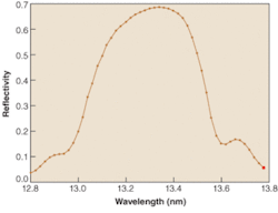
These Mo/Si mirrors are analogous to visible-light dielectric mirrors, and have achieved normal-incidence reflectivities as high as 70% in the EUV region of the spectrum. Before their development in the mid-1980s, such high reflectivities in this spectral region were obtained only with grazing-incidence optics that were poorly suited to high-volume, diffraction-limited imaging because of the difficulty in simultaneously achieving high collection angles and small aberrations. The normal-incidence reflectivity of a typical EUV-lithography mirror is centered at 13.5 nm with a bandwidth of about 4% (see Fig. 1). Multilayer stacks have been engineered to include additional intermediate layers to prevent interdiffusion at the Mo/Si interface, keeping the transition between layers sharp to maintain high peak reflectivities over time.
Mirror reflectometry
At the heart of the photolithographic process is a tool called the stepper, comprising a source, a condenser to illuminate a mask, the mask with the pattern to be replicated, and projection optics to demagnify and image the pattern onto the resist-coated wafer. The first incarnation of a full-scale EUV-lithography stepper was the Engineering Test Stand (ETS) constructed as the centerpiece of the EUV LLC consortium.1 The condenser of the ETS had both multilayer mirrors working at near-normal incidence and metallic grazing-incidence mirrors. The projection optics were all multilayer mirrors in near-normal-incidence configurations.
The complex surfaces of stepper optics require precise reflectivity maps. These are best obtained with inherently stable synchrotron sources. The National Institute for Standards and Technology (NIST; Gaithersburg, MD) has been conducting EUV reflectometry measurements since 1993 on its Synchrotron Ultraviolet Radiation Facility (SURF III). The EUV reflectometry beamline incorporates a monochromator using a 600 mm-1 variable line-spaced grating to operate in the 13.5-nm spectral region with resolving power of 200. Scattered out-of-band radiation in this region of the spectrum can lead to significant errors in reflectivity measurements. The NIST system uses two filters: a beryllium (Be) filter that strongly suppresses the second-order contribution and a zirconium/silicon (Zr/Si) filter directly deposited on the measuring photodiode that further narrows the EUV pass band. In addition, SURF III is readily tunable from its standard electron-beam energy of 380 MeV, where its output spectrum is peaked near 13.5 nm, to lower energies where the peak occurs at longer wavelengths-thus providing an additional variable to help in characterizing spectral purity.2 We have modeled the effects of broad out-of-band scatter and higher-order grating contamination with an estimated uncertainty of 0.35% in correcting for these factors.
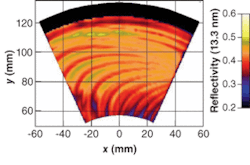
The reflectometer at NIST can handle 15-cm-thick EUV-lithography optics up to 35 cm in diameter, and measure angles of incidence from 3.5° to 88°. An EUV reflectivity map of a portion of the normal-incidence condenser optic taken from the ETS after significant use shows significant damage due to sputtering, debris deposition, and heating by the xenon (Xe) laser-produced plasma source that was nearby (see Fig. 2). The reflectivity map of the condenser optic and other surface analyses were part of a comprehensive SEMATECH (Austin, TX) study aimed at mitigating optics degradation in the stepper.
Because of the way in which the diffraction limit and flare scale with wavelength, the figure and surface-roughness tolerances on the projection mirrors are stringent. The ETS, which successfully demonstrated the technical viability of EUV lithography, has been superceded by two newer tools: the Excitech MS-13, which is based on a two-element limited-field (200 × 600‑mm) projector, and the ASML Alpha tool, which is based on a six-element full-field (2 × 26 mm) projector.3 The figure, mid-, and high-spatial-frequency roughness for the objective optics in both tools is between 0.20- and 0.35-nm root mean square (rms). In the figure-error budget, the allowed value of 0.05 nm is 0.02% of the total coating thickness of approximately 300 nm, implying that the center wavelength of a coating’s reflectivity must be manufactured with a precision of 3 pm. There is also a tolerance of 14 pm on the wavelength accuracy of the centroid to ensure the matching of the reflectance curves of each mirror of the multimirror system. EUV reflectometry must have the capability to measure the performance of coatings with better precision and accuracy than the manufacturing specifications.
Extending mirror lifetime
Such stringent reflectivity requirements make EUV-lithography optics very expensive to fabricate and align, meaning that commercial viability will require operating lifetimes of 30,000 hours. Because the vacuum environment of an EUV stepper cannot be baked, the optics are exposed to significant partial pressures of water vapor and various hydrocarbons in the presence of intense EUV radiation. Interaction of the energetic 13.5-nm (91.8-eV) photons with these residual gas molecules adsorbed onto the mirror surface can damage the mirror, leading to decreased reflectivity. For example, a conventional Si-terminated Mo/Si mirror in an EUV-lithography environment containing just 10-4 Pa of water vapor would have a lifetime of only a few hours before oxidation of the top Si layer reduced the reflectivity below acceptable limits.
To extend this woefully short lifetime, researchers have developed multilayer mirrors with protective overlayers. A capping layer must be resistant to oxidation and yet not be so absorbent as to degrade the reflectivity of the mirror. To date, 2 nm of ruthenium (Ru) on top of a multilayer has been shown to extend the lifetime in the presence of water vapor and EUV radiation to a few hundred hours.4 While this is still far short of the required lifetime, much better performance is expected from capping layers currently under development.
Residual hydrocarbons in the stepper environment present a different problem: the growth of EUV-absorbing carbon deposits on top of the capping layer. Carbon-removal techniques have been successfully demonstrated in which atomic oxygen, ozone, or hydrogen are used to remove carbon from the surface.5 Work is still continuing in this area, but such periodic cleaning techniques would consume valuable production time and may lead to nonuniform reflectivities on larger optics.
Another possible approach is to balance the carbon produced from hydrocarbons cracked by EUV photons with the production of water-dissociated oxygen and hydroxide radicals in a continuous cleaning mode that simultaneously eliminates both the carbon deposition and the oxidation. This effect is believed to be the mechanism behind the oxidation mitigation observed when simple hydrocarbons like ethanol and methanol are admitted during EUV exposure of multilayer mirrors.6
Obviously, direct verification of the required 30,000-hour lifetime for each newly developed capping layer is not feasible. Instead, the scaling of the damage mechanisms must be characterized well enough to allow extrapolation of the years-long lifetime of the optic in the stepper environment from a few hundred hours of accelerated test exposures under more aggressive conditions. To pursue this challenge, NIST has a dedicated beamline on SURF III that can deliver up to 6 mW/mm2 of in-band EUV radiation in an environment of controlled water or hydrocarbon partial pressures. Beginning with the first uncapped multilayer mirror, this facility has been used to benchmark the endurance of novel capping layers under anticipated stepper conditions of moderate water and hydrocarbon partial pressures (10-7 to 10-5 Pa). Accelerated tests at partial pressures as high as 7 × 10⁻⁴ Pa have also been carried out (primarily) on Ru-capped multilayers to determine how damage scales with varying levels of light intensity, and water and hydrocarbon concentrations.7
Contrary to expectations, these investigations revealed that, for fixed exposure duration and intensity, the damage to the Ru-capped mirror surface actually decreased with increasing partial pressures of water above approximately 6 × 10⁻⁴ Pa (see Fig. 3). The mechanism behind this unexpected behavior is not yet fully understood, but preliminary tests have shown that the admitted water itself is not the source of the hydrocarbons and that the partial pressures of carbon-containing constituents of our vacuum increase sublinearly with the partial pressure of water.
While these observations may have important implications for creating long-lived optics for EUV lithography, they also place stringent requirements on the characterization of the testing and operating environment of these optics. For example, the lifetime under actual stepper conditions can be dramatically shorter than that estimated from benchmark exposures if the test environment contains a few parts per 100 greater concentration of carbonaceous species than the stepper environment.❏
REFERENCES
1. S. H. Lee et al., Proc. SPIE4688, 266 (2002).
2. C. Tarrio et al., J. Res. NIST108(4) 267 (2004).
3. H. Meiling et al., Proc. SPIE5751, 90 (2005).
4. S. Bajt et al., Appl. Opt. 42(28) 5750 (2004).
5. H. Oizumi et al., Proc. SPIE5751, 1147 (2005).
6. L. E. Klebanoff, et al, J. Vac. Sci. Tech. A 22, 425 (2004).
7. Ru-capped mirrors were designed and fabricated by Sasa Bajt at LLNL and provided through SEMATECH. Part of this work was performed under the auspices of the U.S. Dept. of Energy by the University of California Lawrence Livermore National Laboratory under Contract W-7405-Eng-48.
STEVE GRANTHAM, CHARLES TARRIO, and SHANNON B. HILL are physicists, and THOMAS B. LUCATORTO is physicist and group leader in the Physics Laboratory at the National Institute of Standards and Technology (NIST), Gaithersburg, MD 20899; e-mail: [email protected].


