Temperature stabilization, as well as optical designs that include more than one gain-flattening filter, keep the gain error function of erbium-doped fiber amplifiers at low levels.
High-performance dense-wavelength-division-multiplexing (DWDM) optical-transport systems for long-haul (less than 800 km) and ultralong-haul (up to 4500 km) applications require many optical amplifiers in concatenation to overcome the span losses, while avoiding optical-electrical-optical conversion. To best achieve this, improvements are being made to the spectral-gain error function of the erbium-doped fiber amplifiers (EDFAs) involved. These improvements include erbium temperature stabilization and very low-error-function thin-film-filtering (TFF) techniques.
EDFA topology
In a typical DWDM EDFA, optically pumped erbium-doped fiber provides the optical gain. A gain-flattening filter (GFF) compensates for the spectral shape of the erbium-doped fiber. At each input and output connector, along with key interstage points, isolation is added to avoid instability caused by reflections from both external and internal sources. Monitoring is provided on the input, mid-stage, and output to allow gain or power control of the EDFA. Mid-stage access is provided to support additional functionality such as span-loss padding, dispersion compensation, or add/drop architectures.
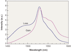
The erbium (Er3+) ions in an EDFA have a variety of allowed energy states.1 If a population inversion is created in the metastable state 4I13/2, stimulated emission can occur in the presence of an input signal at the correct wavelength. In fact, the energy states are broadened via a variety of processes, including stark splitting and thermal broadening. The Giles parameters characterize the unit gain and loss of a specific erbium-doped silica fiber (see Fig. 1).
Spectral optimization
Various EDFA modeling tools are commercially available; these can be used to generate an optical topology that meets the required optical-performance characteristics specified by the customer for their particular system. This sets the overall performance of the EDFA in a reliable manner, but further optimization of the EDFA spectral error function can be undertaken at this point.
Many factors must be considered when designing an EDFA with a low residual gain-shape error. The exact spectral shape of a length of erbium-doped fiber is dependent on the glass host and its doping and chemistry concentrations, output power/gain, temperature, physical length, the wavelength and power of the pump, and the wavelength and powers of the input channels.
Precise understanding of the spectral shape, including any second-order effects, of a length of erbium-doped fiber can most reliably be obtained by using a test bench and procedure that is able to control each of the above variables accurately, so that they can be set to the conditions defined for each specific EDFA design. Measurement accuracies of better than 0.1 dB can be achieved in practice with this approach. As most EDFA designs are operated dynamically for such variables as temperature, input power, and/or channel loading, a series of measurements can be taken to give precise spectral information under each set of conditions, allowing an optimum spectral shape to be ascertained that ensures that the lowest EDFA error function is achieved over the full operating range of the EDFA.
Gain-flattening filter
A C-band (1530- to 1565-nm) EDFA design with an external gain of around 19 dB will have a variation of about 5 dB resulting from the erbium spectral shape. A GFF with the reciprocal function is therefore required to compensate.
Gain-flattening filters benefit from many of the same design techniques and manufacturing processes used to make other telecom filters, such as DWDM bandpass filters. But GFFs are more challenging than typical DWDM filters, for a number of reasons. First, they cover a wide wavelength band (40 nm or more); second, coherently stacked Fabry-Perot resonant-multicavity-filter design techniques used to create low-ripple thin-film filters cannot be directly used on GFFs, which have deep and highly specified “ripple” (5 dB or more).2 And finally, EDFAs are requiring ever-lower gain ripple, resulting in demand for GFFs with ever-tighter error functions.
By using the reciprocal function as the target input to a thin-film-design software program, a dielectric interference filter can be designed. Further optimization is used to achieve the best tradeoff between low error function and the required number of coating layers and/or total layer thickness. Often, designs require more than 100 layers and can be more than 50 µm thick. A robust process should include evaluation of multiple designs generated by the method described above to determine which design is most manufacturable-that is, least susceptible to layer-thickness or refractive-index-variation errors.
Gain-flattening-filter designs often use non-quarter-wave layers and rely on timing rather than optically monitoring layer thickness, so they do not have a self-correcting mechanism. This requires that coating machines capable of tight-tolerance GFFs often control refractive index to 0.05% or better and physical layer thickness to less than 1.0 nm. Use of an automated advanced energetic deposition-coating process such as ion-assisted magnetron sputtering is recommended to achieve both high accuracy and highly stable filters.
A critical part of the component packaging is the shifting of the wavelength by placing the filter at a small angle with respect to the angle of incident light from the input fiber, typically between 1° and 3°. The filter is angle-tuned for the minimum error function. The light signal from the input fiber must be precisely coupled into the output fiber. A total of six degrees of freedom (with micron-scale tolerances) must be accurately aligned to ensure that the full list of filter optical-performance specifications, including low reflectance, are met.
For some EDFA designs with very deep ripple (often called modulation depth) and a very low peak-to-peak error-function (PPEF) specification, a GFF design based on a single filter is not within the current state of the art. One useful solution is to add a second (“tweaker”) filter. The first filter is designed to reduce most of the modulation depth; this filter is then constructed and characterized. The second filter is then designed such that the two filters have a combined overall error function that is significantly lower.
For a specific example in which the EDFA has a preamplifier and booster stage requiring two separate GFFs (14‑dB total modulation depth), the concept has been extended to three filters with a single final “tweaker” filter designed to clean up the previous two filters-reducing the EDFA error function from about 1.5 to 0.4 dB.
Temperature dependence
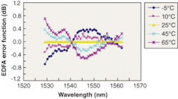
Temperature changes to an EDFA cause modifications to the ion populations in individual sublevel and energy states. These in turn modify the spectral characteristics of the erbium-doped fiber, as well as the inversion level. On top of the static errors described earlier, an EDFA without temperature stabilization might show an error-function change of ±0.7 dB over the operating range of -5°C to +65°C (see Fig. 2).
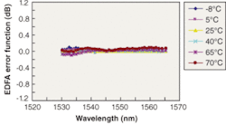
However, techniques now exist to control the temperature of the erbium-doped fiber (see Fig. 3). The most common approach is to heat the erbium fiber to achieve a constant temperature, usually realized by a combination of a resistive heater element and temperature sensor attached to the fiber, along with appropriate thermal management of the assembly. In addition, control circuitry must be incorporated within the design to maintain a constant fiber temperature. Cost-effective but efficient hardware and firmware have been developed that can be implemented within many mechanical designs; indeed this technique is used in most gain-flattened EDFAs sold today.
Design and manufacture
The impact of other components in the optical path (for example, pump multiplexers, couplers, isolators, variable optical attenuators, optical-service-channel filters, and so on) used within the EDFA must be taken into account. Each of these components has a small but quantifiable wavelength-dependent loss. The total magnitude of this is topology-dependent but can be on the order of 0.25 dB, although careful design will remove the majority of this contribution. If a variable optical attenuator or similar device is used, then the wavelength-dependent loss may be a function of the attenuation.
An optimized design is only the start of the story. A successful product requires that the design intent can be met over the product life cycle. To meet this requirement, account of the in-feed component variation must be included in the design, along with steps taken to ensure that these statistics keep within bounds. In addition, the end-to-end manufacturing processes must be continuously monitored to ensure that the build does not drift from the design intent.
REFERENCES
1. E. Desurvire, Erbium Doped Fiber Amplifiers-Principles and Applications, Wiley (1994).
2. H. A. Macleod, Thin Film Optical Filters, Third Edition, IoP Publishing, Philadelphia (1986, 2001).
PAUL JOHNSON is engineering leader at Bookham, Brixham Road, Paignton, Devon, England TQ4 7BE; RAD SOMMER is a senior R&D engineer at Bookham, 3640 Westwind Blvd., Santa Rosa, CA 95403; e‑mail: [email protected] and rad.sommer@bookham.com.


