The scanning range of a MEMS mirror can be increased by adding optics that amplify the scanning angle. This “optical extension” technique allows miniaturization of 3-D real-time imaging ladar systems to a size that opens up many new applications.
Although laser radar (ladar) has been actively pursued by the military and civilian industries for decades, only recently have the techniques of optically extending the scanning range of microelectromechanical-systems (MEMS) mirrors made miniaturization of 3-D real-time ladar possible. This next-generation 3-D ladar will be highly accurate, economical, eye-safe, and small enough to hold in one’s hand.
Today’s scanning 3-D ladar can have greater angular, range, and ultimately better display resolution than alternative imaging techniques. It can be used to “see” targets that are invisible to other imaging devices and has already found many practical applications. Unlike 1-D ladar, which is currently being used by law enforcement to catch speeders, 3-D imaging ladar is being used for target identification, terrain mapping, 3‑D documentation of buildings/objects, robotic navigation, and more. The major barriers to expansion of 3-D real-time ladar are weight and cost-the smallest existing device weighs more than 15 kg and the average cost for 3-D ladar units is about $100,000.1
Next-generation scanning ladar
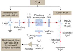
The next-generation scanning 3‑D ladar systems will likely use a pulsed time-of-flight methodology and consist of a clock, pulse generator/driver, laser, scanning MEMS mirror(s), transmitting/receiving scanners, photodetector, and data-acquisition electronics (see Fig. 1). The data obtained from the ladar device can then be visually displayed for the user and/or wirelessly transmitted to a data-collection computer for more in-depth processing. A potential example of the latter would be multiple soldiers at different locations who would use GPS (global-positioning-system) integrated ladar to scan the same field of combat. These multiple input scans would then be transmitted to a central computer to build 3-D maps and identify targets. The key to miniaturizing and making a 3-D real-time scanning ladar affordable, though, is to use innovative components and a tilting MEMS mirror in novel but practical ways.
The pulse generator/driver and laser components for a next-generation scanning 3-D ladar system need to be small and relatively inexpensive; unfortunately the two are often mutually exclusive. One small and potentially inexpensive device that has been designed by LightTime can produce optical pulsewidths of less than 75 ps at any repetition rate from single-shot to 1 GHz at 1310 and 1550 nm. Using such a component at these wavelengths and pulsewidths, along with other design factors, can result in an ANSI Class 1 eye-safe ladar device even with a peak optical pulse power that is hundreds of milliwatts. Also, by using a short pulsewidth and a gigahertz-speed photodetector (typically indium gallium arsenide, which has a high responsivity in the 1300- to 1600-nm range), the range resolution (the smallest radial distance between two distinguishable targets) is about 1 cm; with advanced edge detection and algorithms, it can potentially be reduced to a few millimeters.
Currently, scanning ladar devices often use dual or nodding rotating polygonal mirrors, dual galvanometric mirrors, or a two-axis actuated mirror. All these systems are much larger and require more power than a MEMS-mirror-based system. A MEMS scanning system consists of either two single-axis MEMS mirrors, which operate somewhat more efficiently, or a single two-axis MEMS mirror, which is easier to package. The biggest limitations to the use of either of these MEMS mirror configurations are that their tilt angle is too small (for example, ±8°), they are too slow for real-time imaging, or both. To generate at least 15 frames/second for real-time imaging, the resonant frequency of a MEMS mirror system needs to be at least 1.8 kHz to generate a 320 × 240-pixel image.
Optical extension
By optically extending the scan angle of the MEMS mirror, it is possible to increase the field of view (FOV) of a MEMS-based ladar from as little as 6° to more than 40°. Although diffractive optics and liquid-crystal spatial light modulators can be used, they have resulted in only limited success. A potentially better way is to amplify the angle of the laser beam after it is reflected off the MEMS mirror.
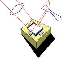
Optical amplification can be accomplished using an optical system that consists of a positive lens prior to the MEMS mirror, followed by a negative angle-amplifying lens after the mirror (see Fig. 2). The purpose of the positive lens is to precompensate for the beam divergence that results from the use of a negative lens for angle amplification. The combination produces an approximately collimated scanning beam. When designed correctly, the laser beam at the MEMS mirror is less than or equal to 0.5 mm in diameter-necessary for most two-axis MEMS scanning mirrors that have a fast-enough resonant frequency for real-time imaging.
The maximum acceptable divergence angle of the beam transmitted from the ladar is determined by the desired spot diameter at the target (the objects being scanned). The positive/negative lens combination produces spot sizes of less than 10 cm at target distances of more than 100 m-a size that, when imaged, is smaller than that represented by a single pixel in a 320 × 240 display.
Another advantage is that by moving the negative lens relative to the mirror, the FOV can be increased or decreased while maintaining the same number of data points, resulting in a zoom effect but without the loss of image resolution that would occur with a conventional digital zoom. Though a similar ladar zoom effect could also be achieved by decreasing the scan angle while using the same number of data points, this would require additional control over the MEMS scanning mirror that is beyond the capability of some units. Either way, a typical 1:4 digital zoom would use just 4800 pixels (80 × 60) of a 76,800-pixel (320 × 240) image, while the ladar zoom would still yield all 76,800 pixels from their unique data points. The ladar zoom in this example would therefore have 16 times more image data points than a digital zoom, providing the ability to obtain high-resolution images from a distance, which is extremely desirable for most applications, and especially for military target identification.
Related improvements
Though using a single laser is a practical option, increasing the number of lasers with different wavelengths would allow data acquisition with lower bandwidth and decreased expense. Or a passively modelocked semiconductor laser could be used with narrow pulse widths; however, their repetition rates (more than 10 GHz) are too fast for full data-acquisition electronics (which operate at 1 to 4‑GHz). As data-acquisition electronics improve, however, this may become an efficient and inexpensive alternative. These modelocked lasers do not need a clock and pulse generator, and produce picosecond pulsewidths that would yield a range resolution of just a fraction of a millimeter. In the design of a miniature scanning 3-D real-time ladar, all the various components must be selected based on the optimal functioning of the ladar device as a whole, within the desired cost and power parameters.
We have proposed designs for miniature 3-D real-time ladar devices using MEMS scanners with an optical display and/or wireless transmitter that would be incorporated into a hat or helmet. Next-generation ladar will likely have at least a 40° FOV, a range resolution of less than 1 cm, capability of outputting range and intensity data from at least 76,800 points per frame, zooming ability without loss of resolution, and can fit into a hand or helmet, all while using less than 4 W of power.
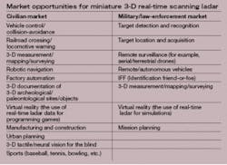
These next-generation ladar devices could be built using current technology at a cost that is at least an order of magnitude less than the large and heavy units in service today, and would have many applications (see table). Next-generation devices could be used to give the blind a form of 3‑D tactile/neural “vision.” A nearer-term major application will be real-time 3-D imaging ladar in the field of robotics, especially for unmanned aircraft and terrestrial vehicles.❏
REFERENCES
1. W. C. Stone et al., NISTIR 7117: www.bfrl.nist.gov/bfrlnews/NISTIR_7117_Final_Complete.pdf.
JAMES P. SIEPMANN is a founder and chief research officer and ADAM RYBALTOWSKI is an electro-optics engineer at LightTime, 375 City Center, Suite Q, Oshkosh, WI 54901; e-mail: [email protected].


