Test and Measurement: Multiple-wavelength interferometry measures large segmented mirrors
The desire to increase the resolving power of Earth- and space-based telescopes has resulted in a new trend of segmenting the primary telescope mirror. The segmentation requires the measurement of potentially large step discontinuities between segments (millimeters) and at the same time requires high-resolution nanometer-scale measurement to verify the surface shape of the elements. While contact profiling and broadband vertical scanning techniques are capable of measuring these discontinuities with the required accuracy, they are slow and cumbersome when measuring large components. Focus and phase-diverse wavefront monitoring methods are ideal for in situ monitoring and alignment of segmented mirror systems; however, they do not measure the wavefront directly and require iterative processes that can require several minutes to converge.
A better method for terrestrial measurements of segmented primary mirrors during manufacturing, alignment, and testing of the adaptive-optic actuators is to use multiple-wavelength interferometry. This technique provides a dynamic range of millimeters while maintaining the high resolution of a single-wavelength interferometer measurement. And, the entire measurement process can be completed in as little as 100 µs.
Segmentation trend
The desire to resolve more closely spaced and distant objects and practical limitations on the size of a monolithic mirror that can be manufactured or deployed in orbit is driving telescope designs to use segmented primary mirrors. The diffraction-limited resolving power of a telescope imposes a practical limit on the ability to resolve two closely spaced point sources such as distant stars—a feat that cannot be circumvented by a simple increase in magnifying power.
For a telescope, the minimum angle that can be resolved is proportional to the wavelength of the light and inversely proportional to the diameter of the primary mirror. Since the observed wavelength of light is usually fixed by the science, the only realistic degree of freedom in the telescope design for improving the resolving power is to increase the diameter of the primary mirror. Unfortunately, at some point it becomes impractical to manufacture the mirror in one piece; in addition, space-based telescopes must fit into a launch vehicle, imposing further limits on the size of the primary mirror. But by segmenting the primary mirror, it can be collapsed to fit into a launch vehicle. Two examples of this new trend are the dual 10-m-diameter telescopes at the Keck Observatory (Kamuela, HI) and the 6.5‑m James Webb Space Telescope (www.jwst.nasa.gov; see Fig. 1).
Measurement requirements
The segmented designs add several new degrees of freedom to the required metrology for the primary mirror. Not only do they need to be figured correctly, but the segments also have to be coaligned in tip, tilt, and piston. As noted, profilers and image-diverse methods can be used but these methods are either cumbersome or do not measure the surface directly.
An alternative technique that can characterize the surface of the mirror directly, in one measurement, is single-wavelength interferometry. Despite its advantages, traditional single-wavelength interferometry has a limited dynamic range for measuring step discontinuities and can have difficulty with the new degrees of freedom in a segmented mirror. The maximum measurable step discontinuity for the traditional technique is slightly less than one-quarter the wavelength used in the measurement. Fortunately, the dynamic range of an interferometer can be increased through multiple-wavelength techniques.
Multiple-wavelength measurement
In multiple-wavelength interferometry, the dynamic range for measuring step discontinuities is increased by making two measurements at slightly different wavelengths and subtracting the phase. The resulting measurement appears as though it were made at a longer synthetic wavelength, λs, defined in the following equation as:Here, λ1 and λ2 are the wavelengths of the two sources used.1 The synthetic wavelength can be tailored to an application by choosing two or more fixed sources of appropriate wavelength. In addition, a continuum of synthetic wavelengths can be generated using a fixed source and a tunable source. The synthetic measurement is used to predict the phase across step discontinuities, and one of the original phase measurements is used to measure the surface shape with the precision afforded by a single-wavelength measurement. Practically any interferometer configuration can be updated to permit multiple-wavelength measurements by adding additional sources and redesigning the optics and coatings to function at the selected wavelengths.
Example interferometer
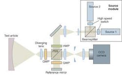
A Twyman-Green interferometer is ideal for measuring large primary mirrors and can be easily adapted to implement the multiple-wavelength technique (see Fig. 2).At the heart of the design is a source module containing two fixed sources that are overlapped and coaligned via a beamsplitter. In front of each source is a fast switch that will facilitate rapid measurements at each of the wavelengths. This particular implementation is a polarizing Twyman-Green interferometer and requires that both sources have their axis of polarization aligned in the same orientation.
Both sources pass through a spatial filter and are collimated before they arrive at the beamsplitter. The half-wave plate is used to rotate the orientation of the incident linear polarization, providing an adjustment for the balance of power between the test and reference beams. The beamsplitter reflects the component of the linear polarization oriented in the vertical direction out toward the segmented test article and allows the horizontal component to pass through to the reference arm of the interferometer. Both the test and reference beams pass through a quarter-wave plate twice which serves to rotate the polarization 90°. Then, the test beam passes through a positive lens that serves two purposes: first, it creates a diverging beam that will match the radius of curvature of the test article; second, it images the test article onto the CCD through a relay. The phase change imparted on the test beam by reflecting off the test article is compared to the phase change imparted on the reference beam and will constitute the measured phase change.
When the test and reference beams arrive back at the beamsplitter, the polarization rotation allows the test beam to pass directly through and reflects the reference beam toward the CCD. The relay moves the image behind the beamsplitter to make space for the CCD, provides a location for the field stop, and can be used to scale the image to fit onto the CCD.
Phase shifting can be implemented either temporally by attaching a piezoelectric transducer (PZT) to the reference mirror or through a simultaneous spatial phase-shifting technique such as a pixilated phase mask.2-7 Multiple-wavelength measurements are made by switching one source at a time into the optical path and taking a measurement at each wavelength. Subtracting the phase of the two measurements provides the increased dynamic range.
Phasing process
The multiple-wavelength interferometer serves three purposes in the testing of a large segmented primary mirror. First, it can be used to phase and align the mirrors directly during manufacturing and testing of the control system. Second, it can confirm the operation of in situ alignment techniques. And finally, it can be used as an in situ measurement technique for terrestrial telescopes.
When phasing a segmented mirror, the starting synthetic wavelength should be at least four times greater than the largest expected step discontinuity to avoid confusion due to the periodic nature of the sine-wave interference fringes. Once the starting synthetic wavelength is determined, the mirrors are aligned in piston, tip, and tilt at that wavelength. Next, the mirror is measured at a shorter synthetic wavelength for which the resolution of the previous alignment step guarantees that the step discontinuities are less than one-quarter of the new synthetic wavelength. The alignment process is then performed at the new synthetic wavelength. This entire process is repeated until the alignment at the shortest synthetic wavelength has sufficient resolution to allow a handoff to one of the fixed wavelengths of the individual sources. At this point, the remaining alignment and figuring can be performed with the resolution of a single-wavelength measurement.
Multiple-wavelength interferometry is an invaluable tool for phasing and measuring segmented primary mirrors. The measurement process is relatively fast, the surface phase is measured directly, and the field of view of the measuring instrument contains the entire mirror. In addition, the dynamic range for measuring step discontinuities is adjustable and the single-wavelength measurements are available to provide high-precision characterization of the surface shape regardless of the synthetic wavelength.
REFERENCES
1. Y.-Y. Cheng and J. C. Wyant, Applied Optics 249(6) 804 (1985).
2. J. C. Wyant and K. Creath, U.S. Patent 8,832,489, “Two wavelength phase-shifting interferometer and method” (May 1989).
3. M. B. North-Morris et al., Proc. SPIE 5531, 64 (August 2004).
4. R. Smythe and R. Moore, Optical Engr. 23(4) 361 (1984).
5. C. Koliopoulos, Proc. SPIE 1531, 119 (1991).
6. J. E. Millerd and N. J. Brock, U.S. Patent 6,304,330 and 6,522,808, “Methods and apparatus for splitting imaging and measuring wavefronts in interferometry” (Oct. 16, 2001).
7.J. E. Millerd et al., Proc. SPIE 5531, 304 (August 2004).
Testing optics large and small
As technologists attempt to characterize the performance of optics as large as space-based telescope mirrors, or as small as cell-phone camera lenses, existing test and measurement methods must be improved or sometimes abandoned in favor of entirely new techniques.
Michael North-Morris of 4D Technology shows how the trend to improve telescope resolution through segmentation of the primary mirror strains existing measurement methods and demands new techniques such as multiple-wavelength interferometry.
Meanwhile, optics in consumer imaging devices are causing scientists like Ben Wells of Wells Research to seek a better understanding of image-quality metrics like modulation transfer function.
And spanning the scale from large to small optics, researchers at Wavefront Sciences are using stitching techniques aided by software algorithms to obtain high-resolution and high-dynamic-range surface measurements.—Gail Overton
About the Author
Michael North-Morris
Senior Director of Product Development, 4D Technology
Michael North-Morris is senior director of product development at 4D Technology (Tucson, AZ).


